
A4 Mk2
 Note
Note
|
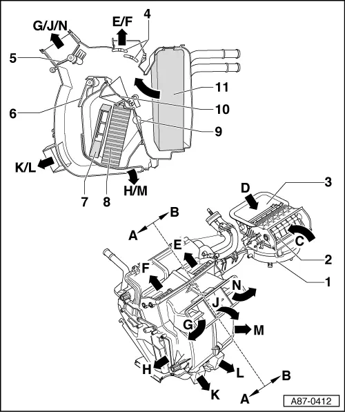
| A - | Driver's side |
| B - | Passenger's side |
| C - | Passenger compartment air intake (recirculated-air mode) |
| q | Via passenger's footwell |
| D - | Fresh-air intake |
| q | Via dust and pollen filter in plenum chamber |
| E - | To windscreen vents (passenger's side) |
| q | The air from the centre defroster vent comes from both sides of the air conditioner unit; its temperature is governed by the mixing ratio arising from the temperature settings made at the operating and display unit, Climatronic control unit -J255- |
| F - | To windscreen vents (driver's side) |
| q | The air from the centre defroster vent comes from both sides of the air conditioner unit; its temperature is governed by the mixing ratio arising from the temperature settings made at the operating and display unit, Climatronic control unit -J255- |
| G - | To dash panel vents, driver's side |
| H - | To front footwell vent, driver's side |
| J - | To dash panel vents, centre |
| q | The air from these vents comes from both sides of the air conditioner unit; its temperature is governed by the mixing ratio arising from the temperature settings made at the operating and display unit, Climatronic control unit -J255- and depending on which flaps are open or closed |
| K - | To rear footwell vent, driver's side |
| L - | To rear footwell vent, passenger's side |
| M - | To front footwell vent, passenger's side |
| N - | To dash panel vents, passenger's side |
| 1 - | Fresh air blower -V2- |
| q | With fresh air blower control unit -J126- |
| 2 - | Recirculated-air flap |
| q | Shown in “closed” position |
| 3 - | Fresh-air flaps |
| q | Shown in “open” position |
| q | The two flaps are actuated independently via the cam plate and actuating arms attached to the control motor. |
| 4 - | Defroster flap |
| q | Shown in “closed” position |
| q | The two flaps are jointly actuated by way of levers and connecting elements attached to the outside of the air distributor housing. |
| 5 - | Central flap “1” |
| q | Shown in “closed” position |
| q | The shape of the two outer flaps is such that air can flow to the left and right vents with the central flap closed. |
| q | The two central flaps are actuated independently via the cam plate and actuating arms attached to the control motor. |
| 6 - | Central flap “2” |
| q | Shown in “open” position, air routing to footwell vents |
| q | The two central flaps are actuated independently via the cam plate and actuating arms attached to the control motor. |
| 7 - | Auxiliary heater element -Z35- |
| q | Only provided for vehicles with diesel engine; electric or fuel-driven supplementary heater depending on vehicle equipment → Chapter, → Auxiliary heating; Rep. Gr.82 and → Diesel direct injection and glow plug system; Rep. Gr.01 |
| 8 - | Heating system heat exchanger |
| 9 - | Temperature flaps “2” |
| q | One flap each for driver's and passenger's side |
| q | Shown in “cooling” position |
| q | The temperature flaps “2” are actuated by the temperature flaps “1” by way of connecting elements in the air distributor housing → Chapter. |
| 10 - | Temperature flaps “1” |
| q | Shown in “cooling” position |
| q | One flap each for driver's and passenger's side |
| 11 - | Evaporator |