| –
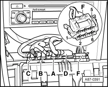
| Plug connectors -D- and -F- to operating and display unit, Climatronic control unit -J255- (all connectors are now plugged in at operating and display unit, Climatronic control unit -J255-). |
| –
| Guide wire to connector -F- contact “1” (contact “2” on right-hand drive vehicles) through 50 A current probe -VAS 5051/9-. |
| –
| On vehicle diagnostic, testing and information system -VAS 5051A-, set “Multimeter measurement: 50 A current probe” mode. |
| –
| Set both knurled wheels for heated seats (at operating and display unit, Climatronic control unit -J255-) to position “0”. |

Note | All connectors must be plugged in at the operating and display unit, Climatronic control unit -J255-. |
| –
| Set knurled wheel for heated driver seat to position “6”. |
| t
| Specification: Display switches from approx. 0 A to less than 10 A |
| –
| Set knurled wheel for heated driver seat to position “0”. |
| t
| Specification: Display switches from less than 10 A to approx. 0 A |
| –
| Guide wire to connector -F- contact “2” (contact “1” on right-hand drive vehicles) through 50 A current probe -VAS 5051/9-. |
| –
| Set knurled wheel for heated front passenger seat to position “6”. |
| t
| Specification: Display switches from approx. 0 A to less than 10 A |
| –
| Set knurled wheel for heated front passenger seat to position “0”. |
| t
| Specification: Display switches from less than 10 A to approx. 0 A |
Note | t
| Interference on the current probe may cause a slight current to be displayed with the seat heating switched off. |
| t
| In the event of an open circuit or a short circuit in the connection to the seat temperature sensor, the output to the heater element is not switched by the operating and display unit, Climatronic control unit -J255-. |
| t
| In the event of a short to earth in the seat heater element or in the wiring, the operating and display unit, Climatronic control unit -J255- does not switch on the heating (immediate deactivation as soon as current is too high). |
| t
| The design of the seat heater elements differs. Depending on heater element design there is thus a possibility of the two side bolsters being constantly heated, e.g. in the event of an open circuit in the seat cushion heater element (the temperature sensor is located in the seat cushion). |
|
|
|
