audi Workshop Repair Guides

Audi Workshop Service and Repair Manuals

Control unit identification (in display zone 2, example) > < Self-diagnosis procedure
Connecting up vehicle diagnostic, testing and information systemVAS 5051A and selecting functions
Connecting up vehicle diagnostic, testing and information system -VAS 5051A- and selecting functions
Test requirements:
t  Vehicle power supply OK
t  Fuses OK → ”Current flow diagrams, Electrical fault-finding and Fitting locations”
  Note
t  The various functions of the vehicle diagnostic, testing and information system -VAS 5051A- are described in the system operating instructions.
t  The design and function of the vehicle diagnostic, testing and information system -VAS 5051A- are described in the → No.202. This also contains a range of examples illustrating correct system utilisation.
t  
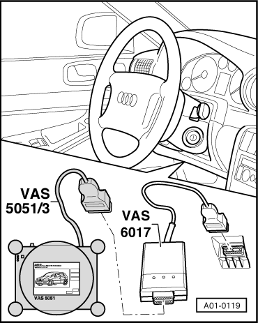
On this vehicle, the diagnostic connections of various control units (e.g. auxiliary heater, radio) are wired to a different diagnostic connector pin. To permit the exchange of data with these control units, the diagnostic wire between the vehicle and the vehicle diagnostic system (e.g. vehicle diagnostic, testing and information system -VAS 5051A- or vehicle diagnostic and service information system -VAS 5052-) must be fitted with a K-wire adapter -VAS 6017B- (or the K-wire adapter -VAS 6017A-) → Chapter and → Current flow diagrams, Electrical fault finding and Fitting locations.
t  On vehicles up to chassis number “399999” in Model Year 2005 (Saloon and Avant) and “012912” in Model Year 2005 (Cabrio) → Parts catalogue, self-diagnosis can also be performed using the fault reader -V.A.G 1551- or the vehicle system tester -V.A.G 1552- in mode “1” (rapid data transfer). The various functions are described in the relevant system operating instructions. On vehicles as of chassis number “400000” in Model Year 2005 (Saloon and Avant) and “012913” in Model Year 2005 (Cabrio), self-diagnosis can no longer be performed for all vehicle systems using the fault reader -V.A.G 1551- or the vehicle system tester -V.A.G 1552-.
t  In order to be able to perform self-diagnosis with the fault reader -V.A.G 1551- or the vehicle system tester -V.A.G 1552- on this vehicle, the program card in the fault reader -V.A.G 1551- must correspond to at least data level “No. 9” and in the vehicle system tester -V.A.G 1552- to at least data level “No. 6”.
   
–  With the ignition switched off, connect up vehicle diagnostic, testing and information system -VAS 5051A- using, for example, diagnostic wire -VAS 5051/5A- and K-wire adapter -VAS 6017B- (or K-wire adapter -VAS 6017A-) to the 16-pin diagnostic socket in the vehicle.
–  Switch on ignition.
Or
–  Start engine.
  Note
t  Pay attention to the applicable notes on final control diagnosis → Chapter.
t  If self-diagnosis is to be performed for several vehicle systems, additional use is to be made if applicable of the K-wire adapter -VAS 6017B- (or the K-wire adapter -VAS 6017A-).
t  The LEDs on the K-wire adapter -VAS 6017- light as soon as the vehicle system tester transmits a request and as soon as the relevant vehicle control unit responds or to indicate the channel (1 or 2) on which the information is output.
–  Set “Auto” mode on the operating and display unit, Climatronic control unit -J255-.
–  Select “Vehicle self-diagnosis” function on vehicle diagnostic, testing and information system -VAS 5051A-.
  A01-0119
–  Select vehicle system “08 - Air conditioner/heater electronics”.
  Note
t  Vehicle system selection prompt appears in display zone -1-.
t  “Scrolling” the screen display with the bar -2- permits display of vehicle systems (for all vehicle models and equipment levels) which are intended for self-diagnosis but are not currently visible on the screen.
  A87-0313
–  Wait until “Select diagnostic function” appears in zone -1- of vehicle diagnostic, testing and information system -VAS 5051A- display.
  Note
t  Control unit identification now appears in display zone -2- of vehicle diagnostic, testing and information system -VAS 5051A- → Chapter.
  A87-0314
t  Check the following if “Vehicle system not available” appears in zone -1- of vehicle diagnostic, testing and information system -VAS 5051A- display:
t  Power supply to operating and display unit, Climatronic control unit -J255- using current flow diagram → Current flow diagrams, Electrical fault finding and Fitting locations
t  Wiring between 16-pin diagnostic socket and operating and display unit, Climatronic control unit -J255-
t  Check the following if an additional display zone -2- with the message “Diagnostic bus fault” and references to possible cause of trouble appears on vehicle diagnostic, testing and information system -VAS 5051A- display:
t  Power supply to 16-pin diagnostic socket using current flow diagram → Current flow diagrams, Electrical fault finding and Fitting locations
t  Voltage and condition of battery -A- (vehicle battery) → "Guided fault-finding" function of vehicle diagnostic, testing and information system VAS 5051 and → Electrical system; Rep. Gr.01
t  “Diagnostic bus fault” display with references to possible cause of trouble also appears on vehicle diagnostic, testing and information system -VAS 5051A- if a problem has occurred during self-diagnosis or in the event of interruption of data exchange between the vehicle diagnostic, testing and information system -VAS 5051A- and the operating and display unit, Climatronic control unit -J255-.
t  The current screen display can be printed out by selecting the “Print” function on the vehicle diagnostic, testing and information system -VAS 5051A- display.
t  Possible causes of trouble can be displayed by selecting “Help” function on vehicle diagnostic, testing and information system -VAS 5051A- display.
t  Touching the keys depicted on the vehicle diagnostic, testing and information system -VAS 5051A- display makes it possible to move forwards or backwards in the program (arrow keys) or to switch functions.
  A87-0315
–  The desired function can now be started by way of the vehicle diagnostic, testing and information system -VAS 5051A- display → Chapter.
  A87-0314

Control unit identification (in display zone 2, example) > < Self-diagnosis procedure