audi Workshop Repair Guides

Audi Workshop Service and Repair Manuals

Connecting elements between temperature flaps "1" and "2" > < Air routing in vehicle
Heating
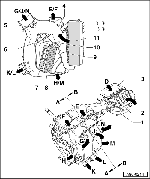
Dash panel vents and air ducts
Air routing in heater
 
A80-0214

Note:

Sectional view of heater shows flaps in "air routing to footwell" position and temperature setting "cold" or setting "min" (no air through heating system heat exchanger).

  •     A -    Driver's side
  •     B -    Passenger's side
  •     C -    Passenger-compartment air intake (recirculated air mode)
    • ◆ Via passenger's footwell
  •     D -    Fresh-air intake
    • ◆ Via dust and pollen filter installed in plenum chamber
 
A80-0214
  •     E -    To windscreen vents (passenger's side)
    • ◆ Air from centre defroster vent comes from both sides of heater; temperature depends on mixing ratio produced by temperature settings on
      -E87 (heating)
  •     F -    To windscreen vents (driver's side)
    • ◆ Air from centre defroster vent comes from both sides of heater; temperature depends on mixing ratio produced by temperature settings on
      -E87 (heating)
  •     G -    To driver's dash panel vents
 
A80-0214
  •     H -    To driver's front footwell vent
  •     J -    To centre dash panel vents
    • ◆ Air from these vents comes from both sides of heater; temperature depends on mixing ratio resulting from which flaps are open/closed and temperature settings on -E87 (heating)
  •     K -    To driver's rear footwell vent
  •     L -    To passenger's rear footwell vent
  •     M -    To passenger's front footwell vent
  •     N -    To passenger's dash panel vents
 
A80-0214
  • Fresh-air blower -V2
    • ◆ With fresh-air blower control unit
      -J126
  • Recirculated-air flap
    • ◆ Fig. shows "closed" position
  • Fresh-air flaps
    • ◆ Fig. shows "open" position
    • ◆ The two flaps are actuated independently of one another by cam plate attached to control motor and actuating arm
  • Defrost flap
    • ◆ Fig. shows "closed" position
    • ◆ The two flaps are jointly actuated by way of levers attached to outside of air distributor housing and connecting elements
 
A80-0214
  • Central flap 1
    • ◆ Fig. shows "closed" position
    • ◆ Due to the shape of the two outer flaps air can flow to left and right vents when centre flap is closed
    • ◆ The two central flaps are actuated independently of one another by cam plate attached to control motor and actuating arm
  • Central flap 2
    • ◆ Fig. shows "open" position, air routing to footwell vents
    • ◆ The two central flaps are actuated independently of one another by cam plate attached to control motor and actuating arm
 
A80-0214
  • Additional heating heater element
    -Z35
    • ◆ For vehicles with diesel engine only; electric or fuel-driven additional heater depending on vehicle equipment and

=> Relevant Diesel Direct-injection and Glow Plug System Workshop Manual; Repair Group 01

  • Heating system heat exchanger
  • Temperature flaps 2
    • ◆ One flap each for driver's and passenger's side
    • ◆ Fig. shows "cold" position or "Min" setting
    • ◆ Temperature flaps 2 are actuated by temperature flaps 1 by means of connecting elements in air distributor housing => Page 80-57
 
A80-0214
  • Temperature flaps 1
    • ◆ Fig. shows "cold" position or "Min" setting
    • ◆ One flap each for driver's and passenger's side
  • Noise insulation
    • ◆ For air routing and noise insulation (instead of evaporator on vehicles with air conditioner)

Connecting elements between temperature flaps "1" and "2" > < Air routing in vehicle