
A4 Mk2
|
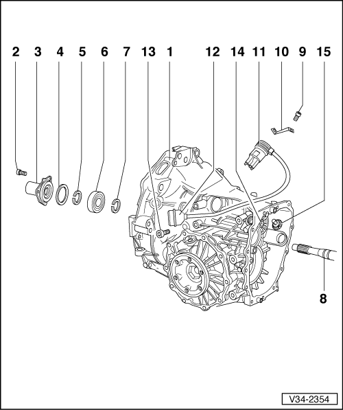
| 1 - | Gearbox housing |
| q | Housing manufactured from aluminium or magnesium → Item |
| q | With differential and flange shafts |
| q | Removing and installing flange shafts → Chapter „Renewing flange shaft oil seal (left and right)“ |
| q | Removing and installing differential → Chapter |
| q | Removing and installing speedometer sender and drive wheel → Chapter |
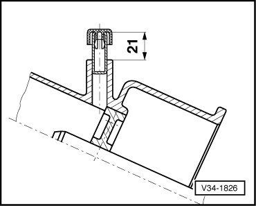
| q | Installation position of breather → Fig. |
| q | Breather made of different materials for aluminium and magnesium gearboxes |
| q | For correct version, refer to → Electronic parts catalogue |
| 2 - | Torx socket head bolt |
| q | Self-locking |
| q | Always renew |
| q | Black: only for aluminium gearboxes |
| q | Bright metal: for aluminium and magnesium gearboxes |
| q | For correct version, refer to → Electronic parts catalogue |
| q | Tighten to 35 Nm on aluminium gearboxes |
| q | Tighten to 25 Nm on magnesium gearboxes |
| 3 - | Guide sleeve |
| q | With O-ring and oil seal for input shaft → Chapter |
| q | Pack space between sealing lip and dust lip half-full with sealing grease -G 052 128 A1-. |
| q | Installation position: Oil drain hole points downwards. |
| q | Guide sleeve is made of different materials for aluminium and magnesium gearboxes |
| q | For correct version, refer to → Electronic parts catalogue |
| 4 - | Dished spring |
| q | Smaller diameter (convex side) faces guide sleeve |
| 5 - | Circlip |
| q | Determining thickness → Chapter „Adjusting input shaft“ |
| 6 - | Ball bearing |
| q | Removing and installing → Chapter |
| 7 - | Circlip |
| q | Determining thickness → Chapter „Adjusting input shaft“ |
| 8 - | Input shaft |
| q | Removing and installing → Chapter |
| q | Dismantling and assembling → Chapter |
| q | Adjusting → Chapter |
| q | Servicing input shaft bearings → Chapter |
| 9 - | Bolt |
| q | Black: only for aluminium gearboxes |
| q | Bright metal: for aluminium and magnesium gearboxes |
| q | For correct version, refer to → Electronic parts catalogue |
| q | Tighten to 25 Nm on aluminium gearboxes |
| q | Tighten to 15 Nm on magnesium gearboxes |
| 10 - | Locking plate |
| q | For multi-function sender |
| q | Locking plate made of different material for aluminium and magnesium gearboxes |
| q | For correct version, refer to → Electronic parts catalogue |
| 11 - | Multi-function sender |
| 12 - | Connector for multi-function sender |
| 13 - | Bolt |
| q | 10 Nm |
| q | Black: only for aluminium gearboxes |
| q | Bright metal: for aluminium and magnesium gearboxes |
| q | For correct version, refer to → Electronic parts catalogue |
| 14 - | Cover for selector shaft |
| q | Removing and installing → Chapter |
| 15 - | Locking unit for 5th gear and reverse gear |
| q | Removing and installing → |
|
|