
A4 Mk2
| Removing gearbox on vehicles with 4-cylinder engine |

| Special tools and workshop equipment required |
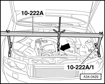
| t | Support bracket -10 - 222 A- |
| t | Lifting tackle -2024 A- |
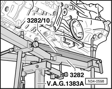
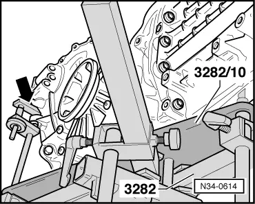
| t | Gearbox support -3282- |
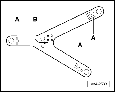
| t | Adjustment plate -3282/10- |
| t | Engine and gearbox jack -V.A.G 1383 A- |
| t | Grease for clutch plate splines -G 000 100- |
| t | Copper grease -Z 381 351 TE- |
 Note
Note
|
 WARNING
|
|
|
|
|
|
|
|
|
|
|
|
|
|
|
|
|
|
|
|
|
|
|
|
|
|
Note
|
|
Note
|
|
|
|
|
|
Note
|
|
|
|
|
|
|
|
|
|
Note
|
|
|
|
Note
|
|
|
|
|
|
Note
|
|
Note
Note
|
|
|
|