audi Workshop Repair Guides

Audi Workshop Service and Repair Manuals

Removing and installing gearbox > < Removing and installing selector mechanism
Adjusting selector mechanism
  Note
t  The following are prerequisites for correct gear lever alignment:
t  Gear selector linkage must be in proper condition and undamaged.
t  Selector mechanism must move freely.
t  Gearbox, clutch and clutch mechanism must be in proper condition.
t  Gearbox in neutral.
   
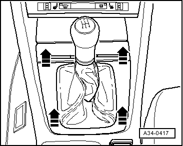
–  Lift off cover for centre console -arrows- and pull cover up and over gear knob.
  A34-0417
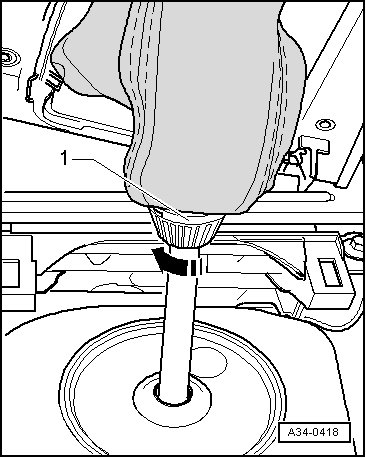
Gear knob with locking mechanism:
–  Release connecting piece -1- in direction of arrow and pull gear knob off upwards together with gear lever boot.
  A34-0418
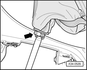
Gear knob with clip:
–  Cut through clip -arrow- using side-cutting pliers or similar and detach gear knob together with gear lever boot upwards.
Vehicles with large radio slot:
–  Remove operating and display unit for air conditioner → Air conditioning system; Rep. Gr.87.
  A34-0529
Vehicles with small radio slot:
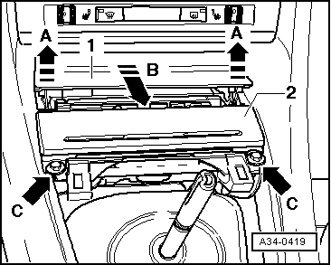
–  First lift trim panel -1- in direction of -arrow A-, then pull it out in direction of -arrow B-.
All models:
–  Unscrew bolts -arrows C- and then pull ashtray -2- out of centre console.
  A34-0419
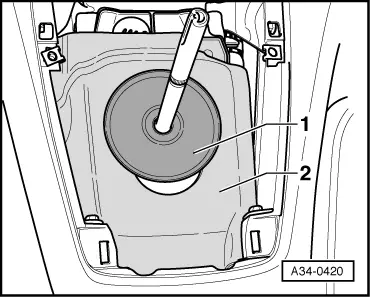
–  Lift out the damping washer -1- and the noise insulation -2-.
  A34-0420
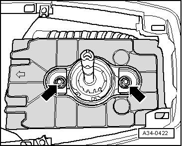
–  Unscrew noise insulation for selector housing -arrows-.
  A34-0422
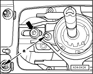
–  Measure distance -a- between the two studs in the selector mechanism.
l  Specification: distance -a- = 85 mm
  Note
Measure from centre of one stud to centre of the other.
If distance -a- does not meet specification:
–  Loosen bolt -arrow- for push rod.
l  Gear lever bearing (in selector mechanism) should move freely in both directions on slide.
–  Set to distance -a- by moving gear lever bearing (in selector mechanism).
–  Tighten bolt for push rod -arrow- to specified torque.
  A34-0424
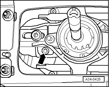
–  Loosen bolt for selector rod -arrow-.
l  Connection between selector rod and selector mechanism should move freely.
  A34-0425
Align the gear lever as follows:
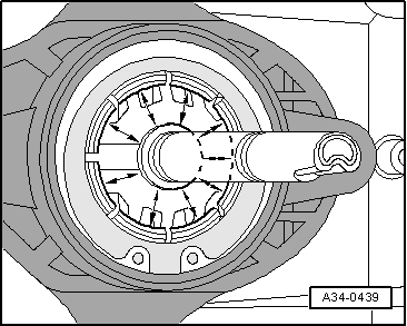
–  Centre the bottom of the gear lever in the centre of the ball guide.
l  Distance between ball guide and bottom of gear lever -arrows- must be the same at all points.
l  Gear lever is vertical in direction of travel.
–  Hold gear lever in this position.
  A34-0439
–  Tighten securing bolt for selector rod -arrow- to torque.
  Note
The gear lever must remain in the same position while the bolt is being tightened.
–  Now check adjustment of selector mechanism → .
  A34-0425
–  Secure noise insulation for selector housing -arrows-.
l  Installation position: arrow marked on noise insulation points in direction of travel.
  A34-0422
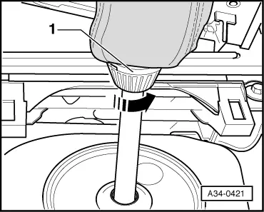
Gear knob with locking mechanism:
–  Push gear knob together with boot onto gear lever and screw down connecting piece -1- in direction of -arrow- as far as stop.
  A34-0421
Gear knob with clip:
–  Fit gear knob with new clip -arrow- onto gear lever and secure using hose clip pliers -V.A.G 1275-.
Tightening torques
  A34-0529
Component Nm
Selector rod to selector fork/gear lever25
Push rod to gear lever bearing25
Noise insulation to selector housing10

Checking adjustment of selector mechanism
l  The gear lever should rest in the 3rd/4th gear gate when the gearbox is in neutral.
–  Depress clutch.
–  Check that all gears can be engaged.
l  When changing through the gears the gear lever must not touch the centre console cover.
l  The gear lever should return by itself from the 5th/reverse gate into the 3rd/4th gate.
l  It should only be possible to engage reverse gear after moving the gear lever into the 3rd/4th gate in neutral.
l  It should not be possible to select reverse gear directly from 5th gear.
  Note
If it is possible to select reverse gear directly from 5th gear, or if only 5th gear and reverse cannot be engaged, the locking unit for 5th and reverse gear should be checked and if necessary renewed → .
   

Removing and installing gearbox > < Removing and installing selector mechanism