
A4 Mk2
| Dismantling and assembling selector mechanism in gearbox |

| Special tools and workshop equipment required |
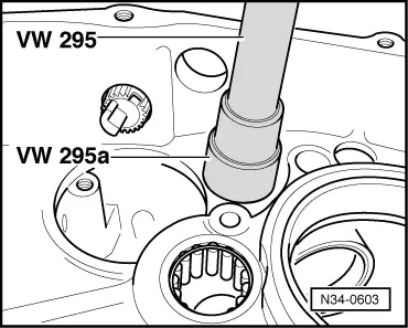
| t | Drift -VW 295- |
| t | Adapter -VW 295 A- |
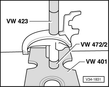
| t | Thrust plate -VW 401- |
| t | Tube -VW 420- |
| t | Tube -VW 423- |
| t | Spacer sleeve -VW 472/2- |
|
|
|
|
|
|
 Note
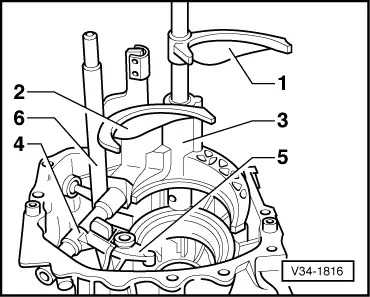
Note| Installation position of complete selector mechanism in gearbox → Fig. |

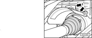
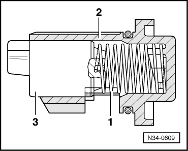
| 1 - | Locking unit for 5th gear and reverse gear |
| q | Removing and installing → |
| 2 - | TORX bolt |
| q | 10 Nm |
| 3 - | O-ring |
| q | Always renew |
| 4 - | Stop bolt (right-side) |
| q | 40 Nm |
| 5 - | Washer |
| 6 - | Relay shaft |
| 7 - | Washer |
| 8 - | Stop bolt (left-side) |
| q | 40 Nm |
| 9 - | Detent segment |
| 10 - | TORX bolt |
| q | 25 Nm |
| 11 - | Spring pin |
| 12 - | Selector fork for 5th gear and reverse gear |
| q | Installation position → Fig. |
| 13 - | Selector rods for 1st/2nd and 5th/reverse gear |
| 14 - | Ball sleeve |
| q | Removing and installing → Fig. |
| 15 - | Selector fork for 1st and 2nd gear |
| 16 - | Follower |
| q | Installation position → Fig. |
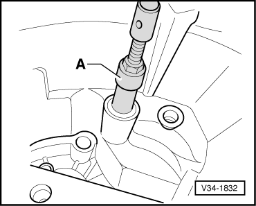
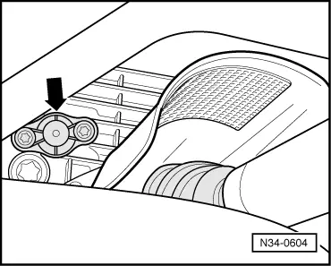
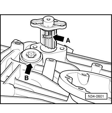
| 17 - | Bearing bush for 3rd and 4th gear |
| q | Pulling out → Fig. |
| q | Driving in → Fig. |
| 18 - | Ball sleeve |
| q | Lever off the selector rod with a screwdriver |
| q | Press onto the selector rod |
| 19 - | Selector rod for 3rd and 4th gear |
| 20 - | Selector fork for 3rd and 4th gear |
| 21 - | Spring pin |
| 22 - | Cover |
| q | For selector shaft |
| 23 - | TORX bolt |
| q | 20 Nm |
| 24 - | Selector shaft |
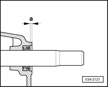
| 25 - | Oil seal |
| q | Lever out with screwdriver |
| q | Use tube -VW 420- to insert |
| q | Installation position → Fig. |
|
|
|
|
|
|
|
|
|
|
|
|
|
|
|
|
|
|
|
|