
A4 Mk2
|
|
|
|
|
|
|
|
|
|
|
|
|
|
|
|
|
|
|
|
|
|
|
|
|
|
|
|
|
|
|
|
|
|
|
|
|
| Component | Nm | |||
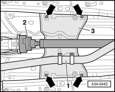
| Selector housing to body | 10 | |||
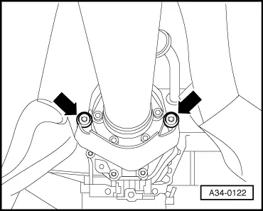
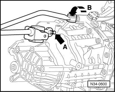
| Selector rod/selector joint to gearbox 1) | 23 | |||
| Push rod to gearbox | 40 | |||
| Noise insulation to selector housing | 10 | |||
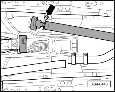
| Clamp for exhaust pipe | 40 | |||
| Propshaft to manual gearbox 1) | 55 | |||
| Heat shield for propshaft to cover for centre differential | 25 | |||
| ||||