
A4 Mk2
| Dismantling and assembling pinion shaft and hollow shaft |
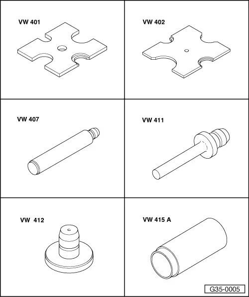
| Special tools and workshop equipment required |
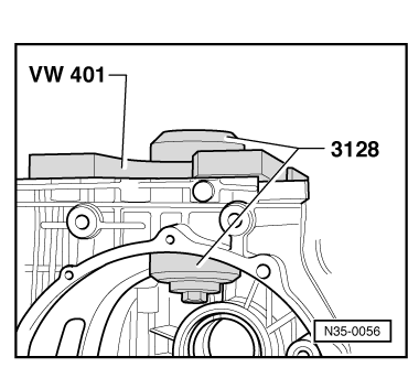
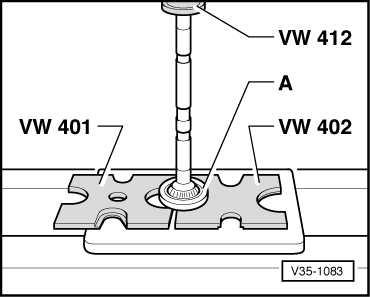
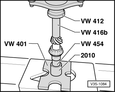
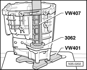
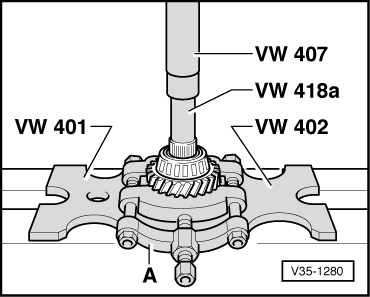
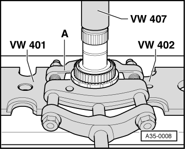
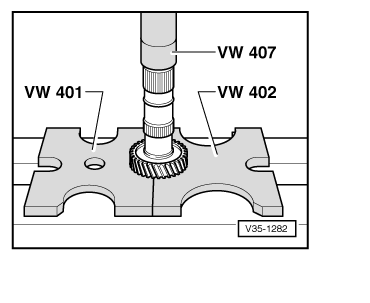
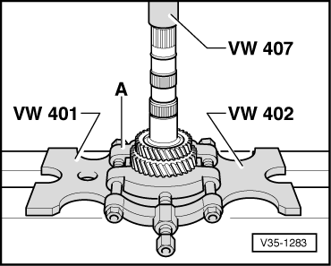
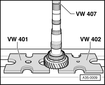
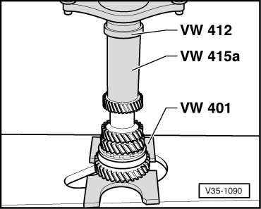
| t | Thrust plate -VW 401- |
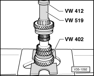
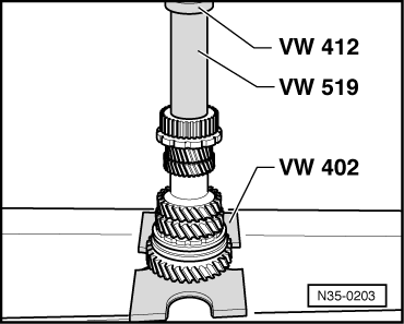
| t | Thrust plate -VW 402- |
| t | Press tool -VW 407- |
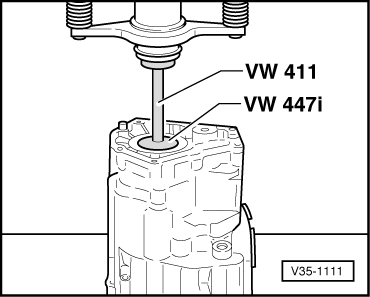
| t | Press tool -VW 411- |
| t | Press tool -VW 412- |
| t | Tube -VW 415 A- |
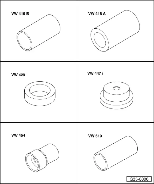
| t | Tube -VW 416 B- |
| t | Tube -VW 418 A- |
| t | Thrust ring -VW 429- |
| t | Thrust plate -VW 447 i- |
| t | Press tool -VW 454- |
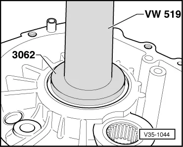
| t | Tube -VW 519- |
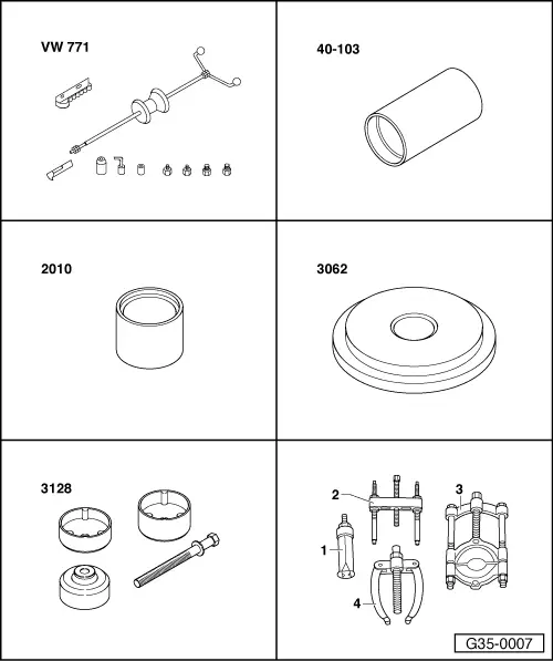
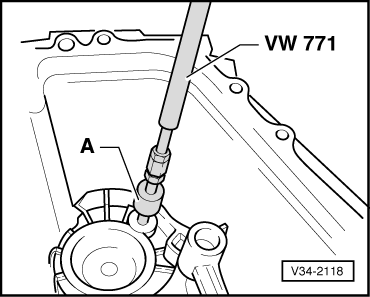
| t | Multi-purpose tool -VW 771- |
| t | Support -40 - 103- |
| t | Tube -2010- |
| t | Thrust pad -3062- |
| t | Fitting tool -3128- |
| t | -1-Internal puller -Kukko 21/1- |
| t | -3-Splitter -Kukko 17/2- |
 Note
Note| t | Refer to technical data → Chapter when installing new gear wheels or the final drive gear set. |
| t | Adjustment work is required when renewing the parts marked with 1) → Chapter. |
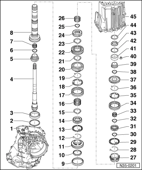
| 1 - | Gearbox housing 1) |
| 2 - | Shim “S3” |
| q | Table of adjustments → Chapter |
| 3 - | Double tapered roller bearing outer race 1) |
| q | Renew together with → Item |
| q | Pulling out → Fig. |
| q | Pressing in → Fig. |
| 4 - | Pinion shaft 1) |
| q | Is mated with crown wheel, always renew together as a set |
| q | Adjusting pinion shaft and crown wheel → Chapter |
| 5 - | Double tapered roller bearing inner race 1) |
| q | Renew |
| q | Will be damaged during removal |
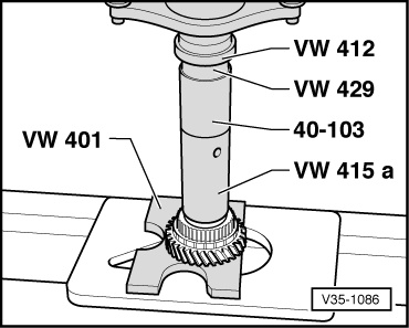
| q | Pressing off → Fig. |
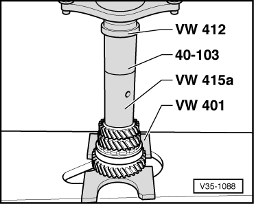
| q | Pressing on → Fig. |
| 6 - | Circlip |
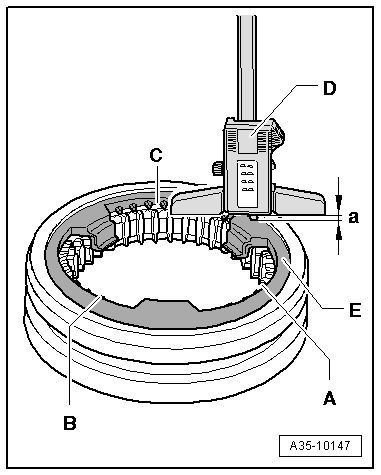
| q | Redetermine thickness if double tapered roller bearing is renewed → Fig. |
| 7 - | Needle bearing |
| q | For pinion shaft in hollow shaft |
| q | Lubricate with MoS2 grease |
| 8 - | Hollow shaft 1) |
| 9 - | Needle bearing for 1st gear |
| 10 - | Needle bearing for 1st gear |
| 11 - | 1st speed selector gear |
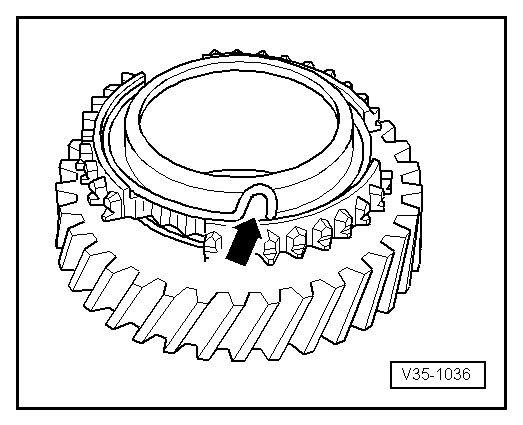
| 12 - | Spring |
| q | Insert in 1st speed selector gear → Fig. |
| q | Allocation to selector gear → Electronic parts catalogue |
| 13 - | Synchro-ring for 1st gear |
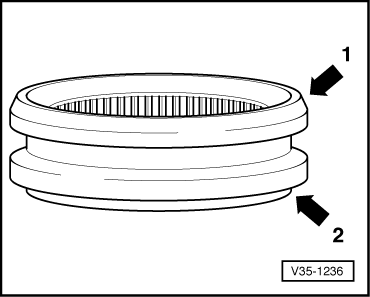
| q | Checking for wear → Fig. |
| 14 - | Synchronising hub for 1st and 2nd gear |
| q | Pressing off → Fig. |
| q | Pressing on → Fig. |
| 15 - | Circlip |
| q | Mark |
| q | Installation position → Fig. |
| q | Redetermine thickness if synchronising hub is replaced → Fig. |
| 16 - | Needle bearing for 2nd gear |
| 17 - | Locking collar for 1st and 2nd gear |
| q | Installation position → Fig. |
| 18 - | Synchro-ring for 2nd gear |
| q | Checking for wear → Fig. |
| 19 - | Spring |
| q | Insert in 2nd speed selector gear → Fig. |
| q | Allocation to selector gear → Electronic parts catalogue |
| 20 - | 2nd speed selector gear |
| 21 - | Circlip |
| q | Mark |
| q | Installation position → Fig. |
| 22 - | 3rd gear wheel |
| q | Pressing off → Fig. |
| q | Pressing on → Fig. |
| 23 - | Circlip |
| q | Mark |
| q | Installation position → Fig. |
| q | If the 3rd gear wheel is renewed determine thickness of required new circlip → Fig. |
| 24 - | 4th gear wheel |
| q | Pressing off → Fig. |
| q | Pressing on → Fig. |
| 25 - | Circlip |
| q | Mark |
| q | Installation position → Fig. |
| q | If the 4th gear wheel is renewed determine thickness of required new circlip → Fig. |
| 26 - | Needle bearing |
| 27 - | 5th speed selector gear |
| 28 - | Spring |
| q | Insert in 5th speed selector gear → Fig. |
| q | Allocation to selector gear → Electronic parts catalogue |
| 29 - | Synchro-ring for 5th gear |
| q | Checking for wear → Fig. |
| 30 - | Circlip |
| q | Mark |
| q | Installation position → Fig. |
| 31 - | 5th gear and reverse gear synchronising hub |
| q | Pressing off → Fig. |
| q | Pressing on → Fig. |
| 32 - | Circlip |
| q | Mark |
| q | Installation position → Fig. |
| q | Redetermine thickness if synchronising hub is replaced → Fig. |
| 33 - | Needle bearing |
| q | For reverse gear |
| 34 - | 5th and reverse gear locking collar |
| q | Installation position → Fig. |
| 35 - | Synchro-ring for reverse gear |
| q | Checking for wear → Fig. |
| 36 - | Spring |
| q | Insert in reverse selector gear → Fig. |
| q | Allocation to selector gear → Electronic parts catalogue |
| 37 - | Reverse selector gear |
| 38 - | Circlip |
| q | Mark |
| q | Installation position → Fig. |
| 39 - | Tapered roller bearing inner race 1) |
| q | Pressing off → Fig. |
| q | Pressing on → Fig. |
| 40 - | Bush |
| q | Secures outer race for small tapered roller bearing |
| q | Pulling out → Fig. |
| q | Need not be fitted after the small tapered roller bearing has been renewed |
| 41 - | Tapered roller bearing outer race 1) |
| q | Pressing out → Fig. |
| q | Pressing in → Fig. |
| 42 - | Shim “S4” |
| q | Table of adjustments → Chapter |
| 43 - | Ring |
| q | For rubber washer |
| q | For correct version, refer to → Electronic parts catalogue |
| 44 - | Rubber washer |
| q | Compensates length variations |
| q | For correct version, refer to → Electronic parts catalogue |
| 45 - | Gearbox cover |
|
|
|
|
|
|
|
|
|
|
|
|
|
|
|
|
|
|
|
|
|
|
|
|
|
|
|
|
| Circlip thickness (mm) | ||
| 1.90 | 1.96 | 2.02 |
| 1.93 | 1.99 | |
|
| Circlip thickness (mm) | ||
| 2.50 |
|
|
| Circlip thickness (mm) | ||
| 1.90 | 1.98 | 2.06 |
| 1.94 | 2.02 | |
|
| Circlip thickness (mm) | ||
| 1.86 | 1.94 | |
| 1.90 | 1.98 | |
|
| Circlip thickness (mm) | ||
| 2.00 |
|
|
| Circlip thickness (mm) | ||
| 1.90 | 1.96 | 2.02 |
| 1.93 | 1.99 | 2.05 |
|
| Circlip thickness (mm) | ||
| 2.50 |
|
|
|
|
|
|
|
|
|
|
|
|
|
|
|
|
|
|
|
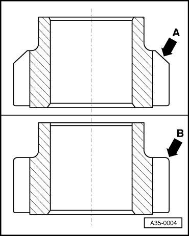
| A | Reverse gear wheel with chamfered surface | Both types of locking collar can be installed (with chamfered surface or with large shoulder) |
| B | Reverse gear wheel without chamfered surface | Install only locking collar with large shoulder; do not use locking collar with chamfered edge |