
A4 Mk2
 Note
Note
|
| Special tools and workshop equipment required |
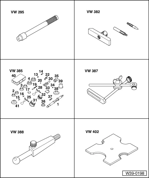
| t | Drift -VW 295- |
| t | Measuring tool -VW 382- |
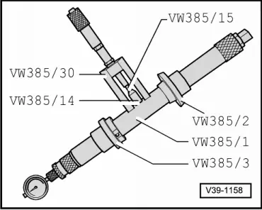
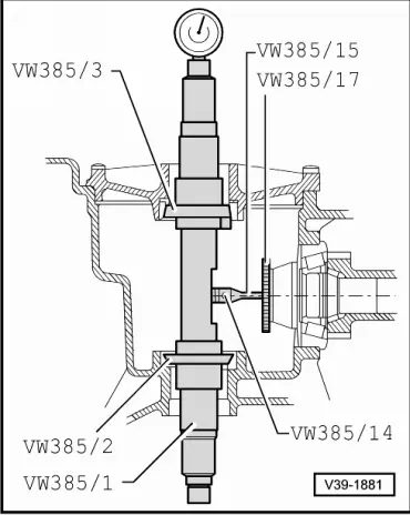
| t | Universal measuring tool -VW 385- |
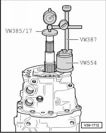
| t | Universal dial gauge bracket -VW 387- |
| t | Measuring lever -VW 388- |
| t | Thrust plate -VW 402- |
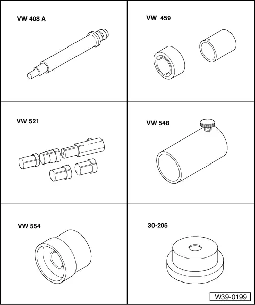
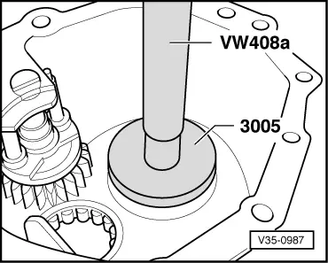
| t | Press tool -VW 408 A- |
| t | Removal and installing tool -VW 459- |
| t | Crown wheel adjusting tool -VW 521- |
| t | Clamp -VW 548- |
| t | Press tool -VW 554- |
| t | Thrust plate -30-205- |
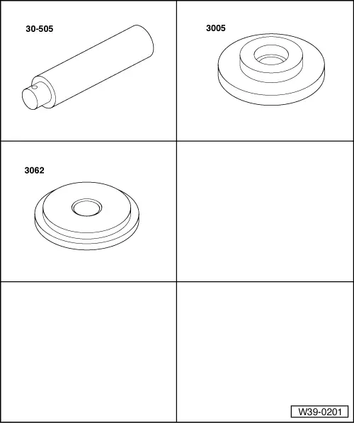
| t | Mandrel -30-505- |
| t | Thrust plate -3005- |
| t | Thrust pad -3062- |
| t | Torque gauge 0 ... 600 Ncm |
| t | Dial gauge |
| t | Dial gauge extension, 30 mm |
|
Note
|
|
Note
|
|
| Example: | |
| Inserted shim “S4*” | 1.00 mm |
| Dial gauge reading (example) | + 0.90 mm |
| Preload (constant value) | + 0.15 mm |
| Total shim thickness “Stotal” for “S3” + “S4” | = 2.05 mm |
|
| Example: | |
| Total shim thickness “Stotal” for “S3” + “S4” | 2.05 mm |
| Inserted shim “S4*” | – 1.00 mm |
| Thickness of shim “S3*” | = 1.05 mm |
|
Note
|
|
|
|
Note
|
|
| Example: | |
| Inserted shim “S3*” | 1.05 mm |
| Deviation “r” | + 0.38 mm |
| Determined value “e” (in red scale) | – 0.16 mm |
| Thickness of shim “S3” | = 1.27 mm |
|
| Available shims - Thickness of shims in mm 1)2) | ||||||
| 0.45 | 0.60 | 0.75 | ||||
| 0.50 | 0.65 | |||||
| 0.55 | 0.70 | |||||
| ||||||
|
| Example: | |
| Total shim thickness “Stotal” for “S3” + “S4” | 2.05 mm |
| Thickness of shim “S3” | – 1.27 mm |
| Thickness of shim “S4” | = 0.78 mm |
|
| Available shims - Thickness of shims in mm 1)2) | ||||||
| 0.45 | 0.65 | 0.85 | ||||
| 0.50 | 0.70 | 0.90 | ||||
| 0.55 | 0.75 | |||||
| 0.60 | 0.80 | |||||
| ||||||
Note
|
|
Note
|

|
|
|