audi Workshop Repair Guides

Audi Workshop Service and Repair Manuals

Clutch, control > < Special tools
Components
Components
Gearbox
t  Select the correct bolts and other components according to gearbox code letters from → Parts catalogue → Chapter „Code letters, allocation, transmission ratios, capacities“.
t  After installing a replacement gearbox, check oil level and fill up with gear oil as required → Chapter.
t  Capacities and specifications → Chapter „Code letters, allocation, transmission ratios, capacities“.
t  Thoroughly clean all joints and surrounding areas before dismantling.
t  When installing gearbox ensure dowel sleeves are correctly seated.
O-rings, oil seals, gaskets
t  
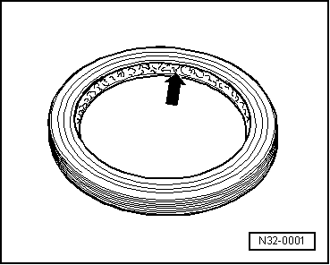
Always install new O-rings, oil seals and gaskets.
t  
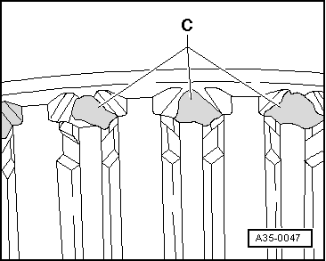
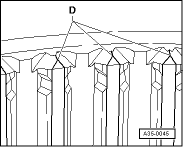
After removing gaskets and seals, always inspect the contact surface on the housing or shaft for burrs resulting from removal or for other signs of damage.
t  Thoroughly clean housing joint surfaces before assembling.
   
t  Before installing oil seals, lightly oil the outer circumference of the seal and fill the space between the sealing lips -arrow- about half full with grease -G 052 128 A1-.
t  The open side of the oil seals faces toward the side with fluid filling.
t  When installing a new oil seal, position the seal in the housing so that sealing lip does not contact the shaft in the same place as the old seal (make use of insertion depth tolerances).
t  Lightly lubricate O-rings before installation to prevent them from being trapped and damaged during assembly.
t  Check oil level in manual gearbox after installing new seals and gaskets → Chapter.
Sealants
t  Thoroughly clean joint surfaces on gearbox housing etc. before applying sealing paste.
t  Apply sealing paste -AMV 188 000 02- or -AMV 188 001 02- evenly and not too thick.
t  Breather holes must remain free of sealing paste.
  N32-0001
Locking elements
t  Do not over-stretch circlips.
t  Renew circlips which have been damaged or over-tensioned.
t  Circlips must be properly seated in the base of the groove.
t  Renew spring pins. Position: the slit -A- should be in line with the line of force -arrow-.
  Note
The spring pin or roll pin which secures the selector fork to the selector rail for 5th and 6th gear may only be removed and installed using press tool -3276-.
Nuts, bolts
t  Loosen the nuts and bolts in reverse sequence to the specified tightening sequence.
t  Nuts and bolts which secure covers and housings should be loosened and tightened in diagonal sequence and in stages if no tightening sequence is specified.
t  Parts which are particularly sensitive (e.g. clutch pressure plates) must be kept straight. Slacken and tighten them in stages and in diagonal sequence.
t  The tightening torques stated apply to non-oiled nuts and bolts.
t  Renew self-locking nuts and bolts.
t  Use a wire brush to clean the threads of bolts which are secured with locking fluid. Then apply locking fluid -AMV 185 101 A1- to bolt threads before installing.
t  Threaded holes which take self-locking bolts or bolts coated with locking fluid must be cleaned (using a tap or similar). Otherwise there is a danger of the bolts shearing off the next time they are removed.
Bearings
t  Install needle bearings so the lettering (side with thicker metal) faces towards the installing tool.
t  Mark needle bearings of 1st to 6th speed selector gears when removing, this ensures that when installing, the same installation position can be guaranteed.
t  Grease needle bearing for gearbox input shaft in rear of flywheel.
t  Lubricate all bearings in gearbox housing with gear oil before installing.
t  Heat inner races of tapered roller bearings to approx. 100°C before installing. Press in onto stop when installing so there is no axial clearance.
t  Do not interchange inner or outer races of bearings of the same size.
t  Always renew the tapered roller bearings on one shaft together and use new bearings from a single manufacturer.
t  The tapered roller bearings for the output shaft and the differential in the gearbox are low-friction bearings. Do not additionally oil new tapered roller bearings when measuring friction torque. The bearings are pre-treated at the factory with a special type of oil for this purpose.
Shims
t  Use a micrometer to measure the shims at several points. Tolerance variations make it possible to obtain the exact shim thickness required.
t  Check for burrs and damage.
t  Do not install shims which are damaged or not in perfect condition.
Gears, synchronising hubs, inner rings for selector gears
t  Heat gears and synchronising hubs to approx. 100 °C before installing. Press in onto stop when installing so there is no axial clearance.
t  Heat inner rings for selector gears to approx. 100 °C when installing.
t  The temperature can be checked with temperature tester -V.A.G 1558-.
t  Note correct installation position.
Selector gears
t  After installing, check selector gears for axial play and freedom of movement.
t  Specification for selector gear (1st gear): 0.15 ... 0.50 mm.
t  Specification for selector gear (2nd to 6th gear): 0.15 ... 0.35 mm.
Synchroniser rings
t  Do not interchange synchroniser rings. When reusing always fit to the same gear.
t  Check for wear; renew if necessary.
t  Lubricate with gear oil when installing.
Synchro-rings with molybdenum coating
  A34-0149
t  The friction surface of an intact synchro-ring with molybdenum coating has a graphite grey, slightly porous appearance. Clean synchro-ring and make sure that friction surface is free of oil.
t  Synchro-ring is to be renewed if very shiny areas -A- have formed on friction surface or if brass-coloured surface underneath is already visible.
  A35-0049
Traces of wear on selector gears or locking collars
t  Traces of wear on synchro-ring or selector gear:
A - Worn ends of splines on synchro-ring or selector gear
  A35-0044
t  In comparison: intact synchro-ring or selector gear:
B - Intact ends of splines on synchro-ring or selector gear
  A35-0046
t  Traces of wear on locking collar:
C - Worn ends of internal splines on locking collar
  A35-0047
t  In comparison: intact locking collar:
D - Intact ends of internal splines on locking collar
t  Always renew synchro-rings with carbon coating together with locking collar. Renew selector gears if there are traces of wear.
Clutch actuation
t  When removing gearbox, remove clutch slave cylinder without disconnecting pipes.
t  Do not depress the clutch pedal after removing the slave cylinder if the hydraulic pipe is still connected. Otherwise the piston will be pressed out of the slave cylinder. As a result the slave cylinder will be destroyed.
t  If the clutch pedal does not return to its initial position after releasing it (clutch pedal in rest position), you must bleed the clutch system.
t  Ensure that the pressure plate is kept straight: loosen and tighten bolts in a diagonal sequence and in several gradual stages.
t  All vehicles are fitted with a SAC pressure plate on which an adjuster ring has to be reset when only the clutch plate is renewed → Chapter.
t  Note assembly instructions for SAC pressure plate → Chapter.
t  If the clutch has burnt out, thoroughly clean the bell housing, flywheel and parts of the engine facing the gearbox in order to prevent odours.
  A35-0045

Clutch, control > < Special tools