
A4 Mk2
| Dismantling and assembling input shaft |
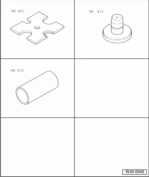
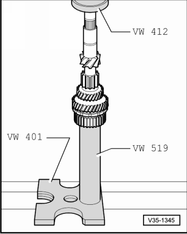
| Special tools and workshop equipment required |
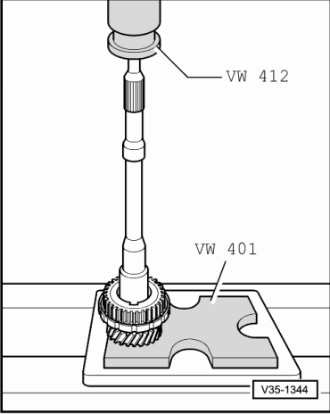
| t | Thrust plate -VW 401- |
| t | Press tool -VW 412- |
| t | Tube -VW 519- |
| t | Feeler gauge |
| Exploded view |
 Note
Note| When installing new gears → Chapter „Code letters, allocation, transmission ratios, capacities“. |
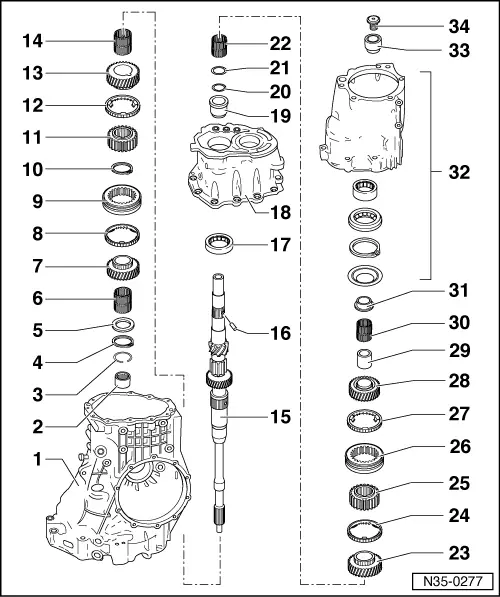
| 1 - | Gearbox housing |
| q | Servicing → Chapter |
| 2 - | Needle bearing |
| q | For input shaft |
| q | Pulling out → Fig. |
| q | Driving in → Fig. |
| 3 - | Circlip |
| q | For needle bearing |
| 4 - | Circlip |
| q | For input shaft |
| 5 - | Thrust washer |
| 6 - | Needle bearing for 4th gear |
| q | Mark before removing |
| q | Do not interchange with needle bearing for 3rd gear |
| q | Lubricate with gear oil before installing |
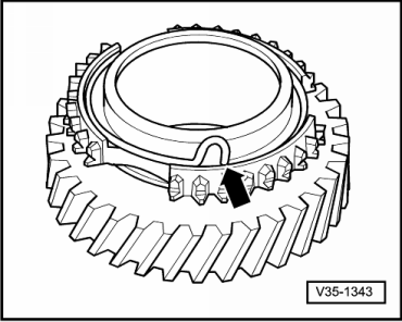
| 7 - | 4th speed selector gear |
| q | Insert spring before installing → Fig. |
| q | After installing, check axial clearance with a feeler gauge (0.15 ... 0.35 mm) |
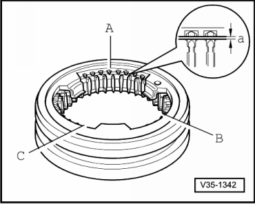
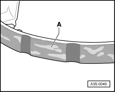
| 8 - | Synchro-ring for 4th gear |
| q | Checking for wear → Fig. |
| 9 - | Locking collar |
| q | Is paired with synchronising hub |
| q | Mark before removing → Anchor |
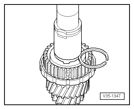
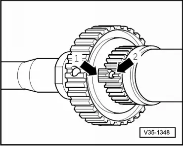
| 10 - | Circlip |
| q | Redetermine thickness if synchronising hub is being renewed → Fig. |
| q | Installation position: ends coincide with groove in synchronising hub |
| 11 - | Synchronising hub for 3rd and 4th gear |
| q | Pressing off → Fig. |
| q | Installation position: → Fig. |
| q | Pressing on → Fig. |
| 12 - | Synchro-ring for 3rd gear |
| q | With molybdenum coating |
| q | Checking for wear → Fig. |
| 13 - | 3rd speed selector gear |
| q | Insert spring before installing → Fig. |
| q | After pressing on → Item, check axial clearance with a feeler gauge (0.15 ... 0.35 mm) |
| 14 - | Needle bearing for 3rd gear |
| q | Mark before removing |
| q | Do not interchange with needle bearing for 4th gear |
| q | Lubricate with gear oil before installing |
| 15 - | Input shaft |
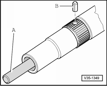
| 16 - | Spring pin |
| q | Drive in when renewing input shaft → Fig. |
| 17 - | Roller bearing |
| q | For input shaft |
| q | Pressing out and pressing in → Fig. |
| 18 - | Intermediate housing |
| q | Servicing → Chapter |
| 19 - | Inner race for roller bearing |
| q | Remove and fit by hand |
| 20 - | Circlip |
| 21 - | Thrust washer for needle bearing for 6th gear |
| q | Installation position: shoulder towards circlip, smooth contact surface towards needle bearing → Anchor |
| 22 - | Needle bearing for 6th gear |
| q | Lubricate with gear oil before installing |
| 23 - | 6th speed selector gear |
| q | Insert spring before installing → Fig. |
| q | After installing, check axial clearance with a feeler gauge (0.15 ... 0.35 mm) |
| 24 - | Synchro-ring for 6th gear |
| q | Checking for wear → Fig. |
| 25 - | Synchronising hub for 5th and 6th gear |
| q | Pulling off → Anchor |
| q | Driving on → Anchor |
| q | Installation position: projecting centre hub towards 5th speed selector gear |
| 26 - | Locking collar |
| q | Is paired with synchronising hub |
| q | Mark before removing → Anchor |
| 27 - | Synchro-ring for 5th gear |
| q | Checking for wear → Fig. |
| 28 - | 5th speed selector gear |
| q | Insert spring before installing → Fig. |
| q | After installing, check axial clearance → Anchor |
| 29 - | Inner race for 5th speed selector gear |
| q | Pulling off → Anchor |
| q | Driving on → Anchor |
| 30 - | Needle bearing for 5th gear |
| q | Lubricate with gear oil before installing |
| 31 - | 1st inner race for input shaft ball bearing |
| q | Pulling off → Anchor |
| q | Driving on → Anchor |
| 32 - | End cover |
| q | Servicing → Chapter |
| 33 - | 2nd inner race for ball bearing for input shaft |
| q | Pulling off → Anchor |
| q | Driving on → Anchor |
| 34 - | Multi-point socket head bolt, 150 Nm |
| q | Loosening and tightening → Anchor |
|
|
Note
|
|
|
|
| Available circlips - Thickness in mm 1) | ||||
| 1.90 | 1.96 | 2.02 | ||
| 1.93 | 1.99 | 2.05 | ||
| ||||
|
|
|
|
|
|
|
 WARNING
|
|