
A4 Mk2
|
| Special tools and workshop equipment required |
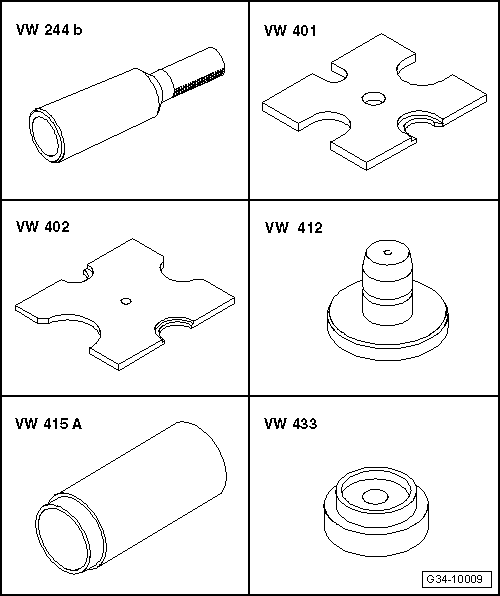
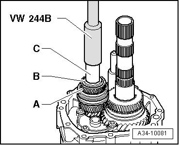
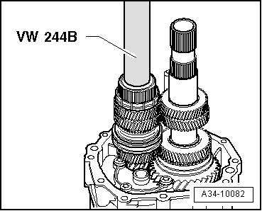
| t | Drift sleeve -VW 244 B- |
| t | Thrust plate -VW 401- |
| t | Thrust plate -VW 402- |
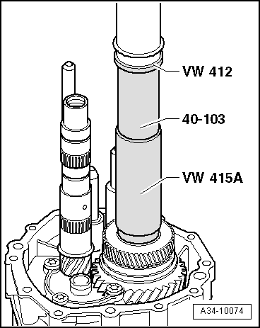
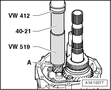
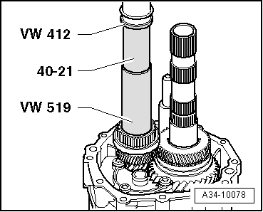
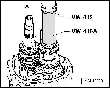
| t | Press tool -VW 412- |
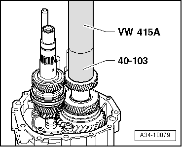
| t | Tube -VW 415 A- |
| t | Press tool -VW 433- |

| t | Tube -VW 519- |
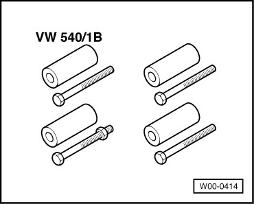
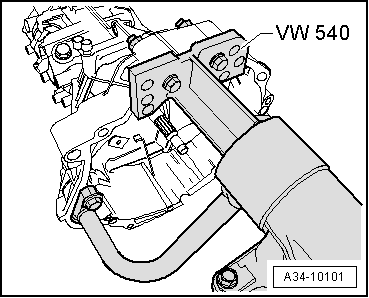
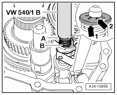
| t | Engine and gearbox support -VW 540- |
| t | Extension -30 - 23- |
| t | Press tool -40 - 21- |
| t | Support -40 - 103- |
| t | Thrust plate -40 - 105- |

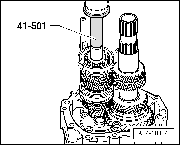
| t | Drift sleeve -41 - 501- |
| t | Gearbox bracket -2004- |
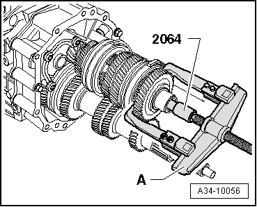
| t | Locking pin -2064- |
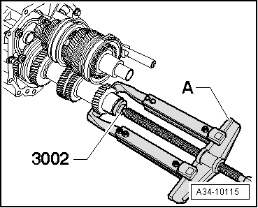
| t | Thrust piece -3002- |
| t | Door hinge alignment tool (M8 and M10) -3114/2- |
| t | Fitting tool -T10246- |
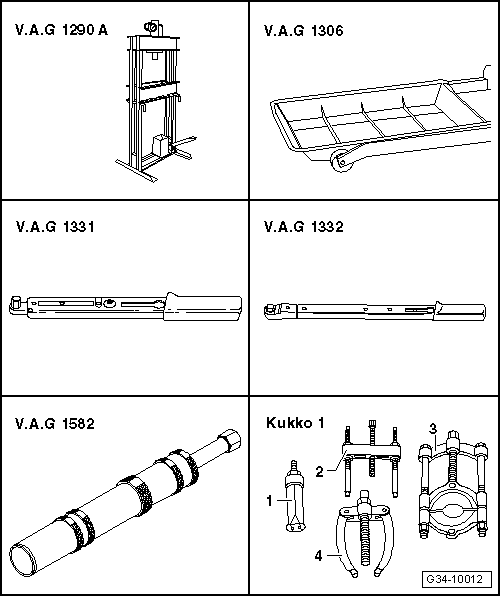
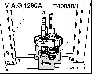
| t | Workshop press -V.A.G 1290 A- |
| t | Drip tray -V.A.G 1306- |
| t | Torque wrench -V.A.G 1331- |
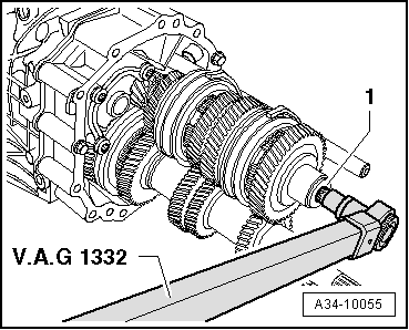
| t | Torque wrench -V.A.G 1332- |
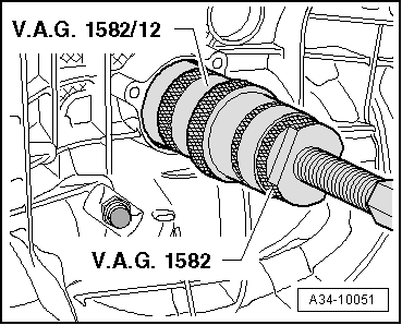
| t | Tapered roller bearing puller -V.A.G 1582- |
| t | Adapter -V.A.G 1582/12- |
| t | -1-Internal puller -Kukko 21/2- |
| t | -2-Puller -Kukko 18/2- |
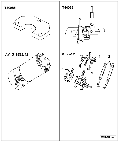
| t | Plate -T40086- |
| t | Plate -T40088/1- |
| t | Adapter -V.A.G 1582/12- |
| t | -1-Two-arm puller -Kukko 20/10- |
| t | -2-Puller hook, length 200 mm |
| t | -2-Puller hook, length 250 mm |
|
|
|
|
|
|
|
|
|
|
 Note
Note
|
|
|
|
Note
|
|
|
|
|
|
|
|
|
|
|
|
|
|
|
|
Note
|
|
 Caution
|
|
|
|
Note
|
|
Note
|
|
|
|
|
|
|
|
Note
|
|
|
|
|
|
|
|
|
|
|
|
|
|
Note
Note
|
|
|
|
|
|
|
|
|
|
|
|
|
|
| Circlip thickness (mm) | ||
| 1.90 | 1.98 | 2.06 |
| 1.94 | 2.02 | 2.10 |
|
|
|
|
|
|
|
|
| Circlip thickness (mm) | ||
| 1.90 | 1.96 | 2.02 |
| 1.93 | 1.99 | 2.05 |
|
Note
|
|
Note
|
|
|
|
|
|
|
|
|
|
|
|
|
|
|
|
|
|
|
|
| Circlip thickness (mm) | ||
| 1.90 | 2.02 | 2.14 |
| 1.93 | 2.05 | 2.17 |
| 1.96 | 2.08 | 2.20 |
| 1.99 | 2.11 | |
|
Note
|
|
|
|
|
|
Note
|
|
|
|
|
|
Note
|
|
|
|
|
|
|
|
|
|
|
|