audi Workshop Repair Guides

Audi Workshop Service and Repair Manuals

Renewing oil seal for selector shaft with gearbox removed (gearbox remains assembled) > < Servicing selector shaft
Removing and installing selector shaft with gearbox installed
Special tools and workshop equipment required
   
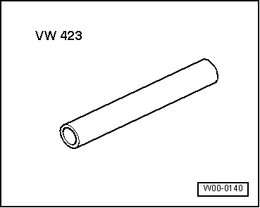
t  Tube -VW 423-
t  Assembly sleeve -01E 311 120-
t  Locking fluid -AMV 185 101 A1-
  W00-0140
Removing
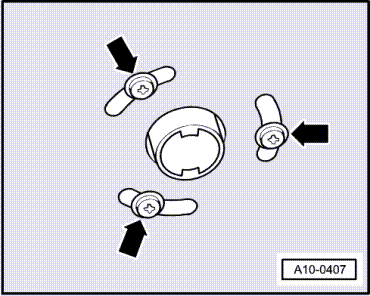
–  On vehicles fitted with auxiliary heater, remove bolts -arrows- securing exhaust pipe of auxiliary/ additional heater to noise insulation.
  A10-0407
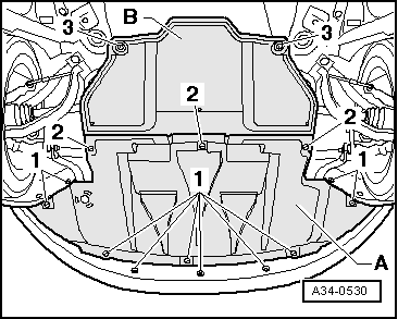
–  Loosen bolts/quick-release fasteners -1- and -2- and remove front noise insulation -A-.
–  If fitted, loosen quick-release fasteners -3- and remove rear noise insulation -B-.
  A34-0530
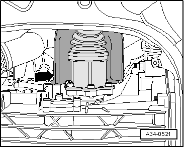
–  Unscrew heat shield -arrow- for drive shaft (right side) and, if fitted, also for drive shaft (left-side).
–  Remove front exhaust pipe (right side) → Rep. Gr.26.
  A34-0521
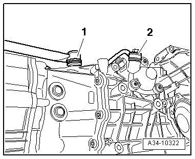
–  Unscrew connecting rod -2- for selector rod.
  Note
-Item 1- can be disregarded.
  A34-10322
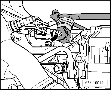
–  Remove nut -arrow- and detach gearbox selector lever from selector shaft.
  A34-10014
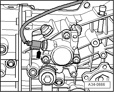
–  Unplug electrical connector -arrow- for reversing light switch -F4-.
  A34-0666
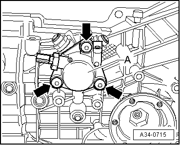
–  Remove bolts -arrows- and take off selector shaft cover -A-.
  A34-0715
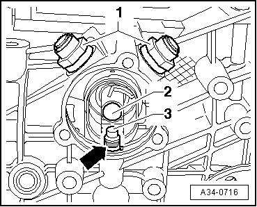
–  Unscrew the two locking bolts -1- for selector shaft.
l  Make sure that no gear has been engaged.
–  Push selector shaft -2- into gearbox as far as it will go, simultaneously removing pin -3-.
–  Pull out selector shaft.
  A34-0716
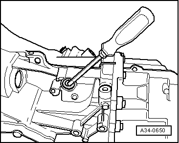
–  Carefully pry out oil seal with a screwdriver.
  A34-0650
Installing
  Note
Renew oil seals and O-rings.
–  Install selector shaft.
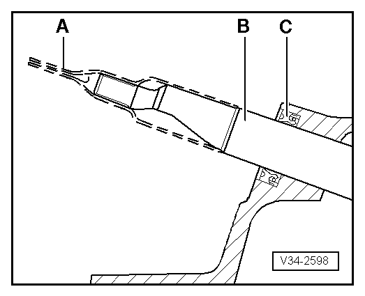
l  Installation position: Chamfer on selector shaft -B- points downwards.
  Note
Ignore -item A- and -item C-.
  V34-2598
–  Push selector shaft -2- into gearbox as far as it will go, simultaneously inserting pin -3-.
l  Installation position: groove -arrow- on pin -3- faces towards selector shaft cover.
–  Clean threads of locking bolts -1- with a wire brush. Then install bolts with locking fluid -AMV 185 101 A1- and tighten to specified torque.
  A34-0716
–  Fit cover -A- with new O-ring.
–  Clean threads of bolts -arrows- with a wire brush. Then install bolts with locking fluid -AMV 185 101 A1- and tighten to specified torque.
  Note
  A34-0715
Use assembly sleeve -01E 311 120--item A- to avoid damaging the oil seal -C- when installing.
  V34-2598
–  Lightly oil outer circumference of oil seal -arrow-.
–  Pack space between sealing lip and dust lip half-full with sealing grease -G 052 128 A1-.
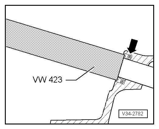
–  Drive oil seal -arrow- into housing as far as it will go.
  V34-2782
–  Install front exhaust pipe and align exhaust system so it is free of stress → Rep. Gr.26.
–  Secure heat shield -arrow- for drive shaft (right-side) and, if fitted, also for drive shaft (left-side) to gearbox.
Tightening torques
  A34-0521
ComponentNm
Locking bolts for selector shaft45
Selector shaft cover24
Connecting rod to gearbox20
Gearbox selector lever to selector shaft20
Heat shield for drive shaft to gearbox23


Renewing oil seal for selector shaft with gearbox removed (gearbox remains assembled) > < Servicing selector shaft