
A4 Mk2
| Exploded view - input shaft |
 Note
Note| t | Refer to technical data when installing new gears → Chapter. |
| t | Lubricate all bearings on input shaft with gear oil before installing. |
| t | The position of the ball bearing → Item will be affected if components → Item or → Item are renewed. In this case the input shaft must be re-adjusted → Chapter. |
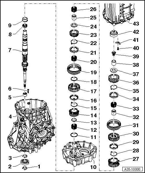
| 1 - | Circlip |
| q | Mark |
| q | Installation position → Fig., -item 1- |
| q | Determining thickness → Chapter „Adjusting input shaft“ |
| 2 - | Ball bearing |
| q | Removing and installing → Chapter „Assembly sequence - dismantling and assembling gearbox“ |
| 3 - | Circlip |
| q | Mark |
| q | Installation position → Fig., -item 2- |
| q | Determining thickness → Chapter „Adjusting input shaft“ |
| 4 - | Gearbox housing |
| 5 - | Needle bearing |
| q | For input shaft |
| q | Secured with bolt → Item |
| q | Removing and installing → Item |
| 6 - | Bolt, 24 Nm |
| q | Secures needle bearing → Item for input shaft |
| 7 - | Input shaft |
| q | Adjusting → Chapter |
| 8 - | Roller bearing |
| q | Detaching and fitting → Fig. |
| q | Installation position: collar faces splines for 2nd gear |
| 9 - | Outer race |
| q | For needle roller bearing |
| q | Removing and installing → Item |
| 10 - | Bearing housing |
| 11 - | Thrust washer |
| q | For 3rd speed selector gear |
| 12 - | Needle bearing |
| q | For 3rd gear |
| 13 - | Circlip |
| q | Mark |
| q | Installation position → Fig., -item 3- |
| 14 - | 3rd speed selector gear |
| 15 - | Spring |
| q | Insert in 3rd speed selector gear → Fig. |
| q | Allocation to selector gear → Electronic parts catalogue |
| 16 - | 3rd gear synchro-ring |
| q | Checking for wear → Fig. |
| 17 - | Synchronising hub for 3rd and 4th gear |
| q | Installation position: high inside collar faces 3rd speed selector gear |
| 18 - | Circlip |
| q | Mark |
| q | Installation position → Fig., -item 4- |
| q | Do not interchange with other circlip → Item |
| q | Re-determining thickness → Fig. |
| 19 - | Locking collar for 3rd and 4th gear |
| q | Mark position in relation to synchronising hub prior to removing |
| 20 - | Needle bearing |
| q | For 4th gear |
| 21 - | 4th gear synchro-ring |
| q | Checking for wear → Fig. |
| 22 - | Spring |
| q | Insert in 4th speed selector gear → Fig. |
| q | Allocation to selector gear → Electronic parts catalogue |
| 23 - | 4th speed selector gear |
| 24 - | Thrust washer |
| q | For 4th speed and 5th speed selector gears |
| 25 - | Needle bearing inner race |
| q | For 5th gear |
| 26 - | Needle bearing |
| q | For 5th gear |
| 27 - | 5th speed selector gear |
| 28 - | Spring |
| q | Insert in 5th speed selector gear → Fig. |
| q | Allocation to selector gear → Electronic parts catalogue |
| 29 - | 5th gear synchro-ring |
| q | Checking for wear → Fig. |
| 30 - | Synchronising hub for 5th and 6th gear |
| 31 - | Locking collar for 5th and 6th gear |
| q | Mark position in relation to synchronising hub prior to removing |
| 32 - | Needle bearing inner race |
| q | For 6th gear |
| 33 - | Needle bearing |
| q | For 6th gear |
| 34 - | 6th gear synchro-ring |
| q | Checking for wear → Fig. |
| 35 - | Spring |
| q | Insert in 6th speed selector gear → Fig. |
| q | Allocation to selector gear → Electronic parts catalogue |
| 36 - | 6th speed selector gear |
| 37 - | Thrust washer |
| q | For 6th speed selector gear |
| 38 - | Inner race |
| q | For needle roller bearing → Item |
| 39 - | Multi-point socket head bolt, 150 Nm |
| 40 - | Multi-point socket head bolt, 24 Nm |
| 41 - | Retaining plate |
| q | Secures needle roller bearing → Item in gearbox cover |
| 42 - | Roller bearing |
| q | Bearing for input shaft in gearbox cover |
| q | With oil guide |
| q | Always renew |
| q | Removing and installing → Item |
| 43 - | Gearbox cover |