audi Workshop Repair Guides

Audi Workshop Service and Repair Manuals

Clutch, control > < Special tools
Components
Components
Gearbox
t  Allocate bolts and other components according to gearbox code letters; refer to → Electronic parts catalogue → Chapter „Code letters, allocation, transmission ratios, capacities“.
t  After installing a replacement gearbox, check oil level and fill up with gear oil as required → Chapter.
t  Capacities and specifications → Chapter „Code letters, allocation, transmission ratios, capacities“
t  Thoroughly clean all joints and connections and the surrounding areas before dismantling.
t  When installing gearbox ensure dowel sleeves are correctly seated.
Sealants
t  Thoroughly clean joint surfaces on gearbox housing etc. before applying sealing paste.
t  Apply sealing paste -AMV 188 001 02- evenly and not too thickly.
t  Breather holes must remain free of sealing paste.
O-rings, oil seals and gaskets
t  
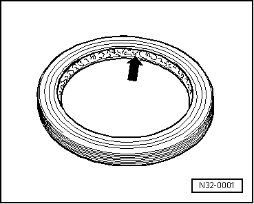
Always renew O-rings, oil seals and gaskets.
t  After removing gaskets and oil seals, always inspect the contact surface on the housing or shaft for burrs resulting from removal or for other signs of damage.
t  Thoroughly clean housing joint surfaces before assembling.
   
t  Before installing oil seals, lightly oil the outer circumference of the seal and fill the space between the sealing lips -arrow- about half full with grease -G 052 128 A1-.
t  The open side of the oil seal should face the side containing the fluid.
t  When installing a new oil seal, position the seal such that the sealing lip does not contact the shaft in the same place as the old seal (make use of installation depth tolerances).
t  Lightly lubricate O-rings before installation to prevent them from being trapped and damaged during assembly.
t  After renewing gaskets and oil seals, check and, if necessary, top up oil level in gearbox → Chapter.
Locking elements
  N32-0001
t  Do not over-stretch circlips.
t  Installation position for some circlips: the circlip is fitted so that the narrow part of the gap is at the top. This also gives the pliers a better grip when removing and installing.
t  Always renew circlips which have been damaged or over-stretched.
t  Circlips must be properly seated in the base of the groove.
  N30-10172
t  Renew spring pins. Position: the slit -A- should be in line with the line of force -arrow-.
  A34-0149
Nuts, bolts
t  Loosen the nuts and bolts in reverse sequence to the specified tightening sequence.
t  Nuts and bolts which secure covers and housings should be loosened and tightened in diagonal sequence and in stages if no tightening sequence is specified.
t  Loosen and tighten particularly sensitive parts in diagonal sequence and in stages, taking care to keep them straight.
t  The tightening torques stated apply to non-oiled nuts and bolts.
t  Renew self-locking nuts and bolts.
t  Use a wire brush to clean the threads of bolts which are secured with locking fluid. Then apply locking fluid -AMV 185 101 A1- to bolt threads before installing.
t  Threaded holes which take self-locking bolts or bolts coated with locking fluid must be cleaned (using a thread tap or similar). Otherwise there is a danger of the bolts shearing off the next time they are removed.
Bearings
t  Lubricate all bearings in gearbox housing with gear oil before installing.
t  Use inductive heater -VAS 6414- to heat inner races of tapered roller bearings to approx. 100°C before installing. Press home onto stop when installing so there is no axial clearance.
t  Do not interchange the outer or inner races of bearings of the same size (the bearings are paired).
t  If required, renew the tapered roller bearings on one shaft together and use new bearings from a single manufacturer.
t  Install needle bearings, ball sleeves and roller bearings so the lettering (side with thicker metal) faces towards the installing tool.
t  Mark the needle bearings of the selector gears when removing. This ensures the same installation position when re-installing.
t  Grease needle bearing for gearbox input shaft in rear of flywheel.
  N00-0383
Shims
t  Use a micrometer to measure the shims at several points. Tolerance variations make it possible to obtain the exact shim thickness required.
t  Check for burrs and damage.
t  Do not install shims which are damaged or not in perfect condition.
Gears, synchronising hubs, inner rings for selector gears
t  Before installing, heat inner rings for selector gears to approx. 100° C using inductive heater -VAS 6414-.
t  Use inductive heater -VAS 6414- to heat gear wheels and synchronising hubs to approx. 100°C before installing. Press home onto stop when installing so there is no axial clearance.
t  Note correct installation position.
Selector gears
t  After installing, check 1st to 6th speed selector gears for minimal axial play and freedom of movement.
  N30-10156
Input shaft
t  Check the input shaft for scoring around the bearing in the crankshaft/flywheel -arrow-. Renew the needle bearing in the crankshaft if necessary → Rep. Gr.13.
Synchro-rings
t  Do not interchange. When reusing synchro-rings, always fit to the same selector gear.
t  Check for wear; renew if necessary.
t  Lubricate with gear oil when installing.
  A34-10780
Checking synchro-rings with molybdenum coating
t  Clean synchro-ring; the friction surface must be free of oil.
t  The friction surface of an intact molybdenum coated synchro-ring has a graphite-grey, slightly porous appearance.
t  The synchro-ring must be renewed if very shiny areas -A- have formed on the friction surface or if the brass-coloured metal underneath is already visible.
  A35-0049
Checking synchro-rings for 1st and 2nd gear
Check the coated contact surfaces -arrows 2- on intermediate ring -B- for damage (flattened sections or particles of carbon coating broken away).
Check inner contact surface -arrow 1- on synchro-ring -A- and outer contact surface -arrow 4- on inner ring -C- for grooves or scoring.
Check for damage to coating on inner rings -C- with coated contact surface -arrow 3- (particles of carbon coating broken away).
  A35-10083
Abnormal wear on selector gears and locking collars
t  Abnormal wear on synchro-ring or selector gear:
A - Worn chamfer on dog teeth of synchro-ring or selector gear
  A35-0044
t  In comparison: intact synchro-ring or selector gear:
B - Intact chamfer on dog teeth of synchro-ring or selector gear
  A35-0046
t  Abnormal wear on locking collar:
C - Worn chamfer on internal splines of locking collar
  A35-0047
t  In comparison: intact locking collar:
D - Intact chamfer on internal splines of locking collar
t  Always renew synchro-rings with carbon coating together with locking collar. Renew selector gears also if there are traces of wear.
Clutch actuation, clutch
t  When removing gearbox, remove clutch slave cylinder without disconnecting pipes.
t  Do not depress the clutch pedal after removing the slave cylinder if the hydraulic pipe is still connected. Otherwise the piston will be pressed out of the slave cylinder. As a result the slave cylinder will be destroyed.
t  If the clutch pedal does not return to its initial position after releasing it (clutch pedal in rest position), you must bleed the clutch system (further measures → Chapter).
t  The clutch system should be bled at the same intervals as the brake system → Booklet45.
t  Note assembly instructions for SAC pressure plate → Chapter.
t  On vehicles with SAC pressure plate an adjuster ring has to be reset when only the clutch plate is renewed → Chapter.
t  If the clutch has burnt out, thoroughly clean the gearbox housing in area of clutch and parts of the engine facing the gearbox in order to prevent odours.
t  Only blow out dual-mass flywheel with compressed air.
  A35-0045

Clutch, control > < Special tools