audi Workshop Repair Guides

Audi Workshop Service and Repair Manuals

Pinion shaft and hollow shaft > < Dismantling and assembling input shaft
Adjusting input shaft
Determining circlips for input shaft ball bearing
It is necessary to readjust the input shaft when the:
t  Gearbox housing
or the
t  Input shaft
are renewed.
Special tools and workshop equipment required
   
t  Drift sleeve -30 - 100-
  W00-0359
t  Door hinge alignment tool (M8 and M10) -3114/2-
  W00-0544
t  Fitting tool -T10246-
t  Digital depth gauge, e.g. -VAS 6087-
Determining thickness for circlip behind input shaft ball bearing
  W00-10225
–  Fit a provisional circlip -arrow- in the rear groove on the input shaft.
–  Then push ball bearing onto input shaft.
Installation position:
The closed side of the ball cage faces the gearbox housing.
  V35-1238
–  Pressing in ball bearing:
First screw pin (M8 and M10) -3114/2- into tapped hole for ball-head pin.
Slide the thrust plate -T10246/2- onto input shaft.
Now position fitting tool -T10246/1- behind splines for clutch plate. Tighten bolts -A- only slightly. The bolts locate in the recesses in the thrust plate -T10246/2-.
Press in ball bearing onto stop by tightening bolts -A- alternately (1/2 turn at a time).
  A34-10123
–  Then fit dished spring -1-.
Installation position:
The convex side faces guide sleeve -2-.
–  Fit a shrink hose onto input shaft splines.
–  Bolt guide sleeve to gearbox housing -2- with bolts -3-.
–  Then turn the gearbox housing so the joint flange for the bearing housing points upwards.
l  The contact surface must be cleaned to remove sealing paste.
  A35-10024
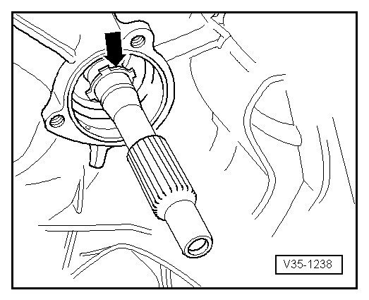
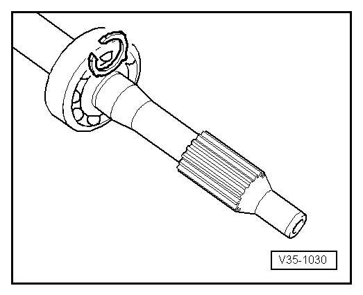
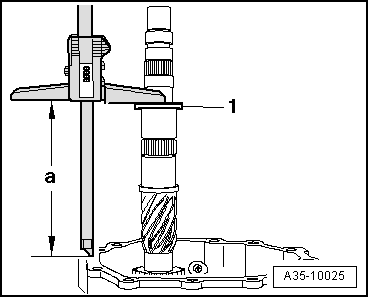
–  Place thrust washer -1- for 4th and 5th speed selector gears onto input shaft.
–  Apply digital depth gauge (e.g. -VAS 6087-) to thrust washer -1- and measure distance to contact surface of housing. The measuring point on the housing contact surface must be as close to the input shaft as possible.
  Note
When measuring, lift the input shaft with e.g. support bridge -30-211A- or the help of a 2nd mechanic so that the play in the ball bearing is taken up.
l  Specification: distance „a“ = 164.14 mm
  Note
t  If the measured value exceeds the specification, use a thinner circlip than the circlip installed so that the specification is attained.
t  If the measured value is below the specification, use a thicker circlip than the circlip installed so that the specification is attained.
t  Determine the circlip thickness to meet the specification as exactly as possible (164.14 mm).
The following circlips are available:
  A35-10025
Circlip thickness (mm)
1.542.082.62
1.632.172.71
1.722.262.80
1.812.352.89
1.902.44 
1.992.53 

–  Select circlip from table. For part number, refer to → Electronic parts catalogue.
   
Checking adjustment and checking distance „a“:
l  Determined circlip is installed.
The distance „a“ should be 164.14 mm ± 0.04 mm if the correct circlip has been selected.
Determining thickness for circlip in front of input shaft ball bearing
–  Knock rear circlip (as determined) and ball bearing onto input shaft using drift sleeve -30 - 100-.
  A35-10025
–  Determine the thickest circlip which will still just fit.
–  Refer to table → Anchor to determine correct circlip. For part number, refer to → Electronic parts catalogue.
  V35-1030

Pinion shaft and hollow shaft > < Dismantling and assembling input shaft