
A4 Mk2
|
|
|
|
|
|
|
|
|
|
|
|
|
|
|
|
|
|
|
 Note
Note
|
|
|
|
Note
|
|
|
|
 WARNING
|
|
|
|
|
|
|
|
| Component | Nm |
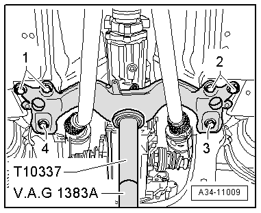
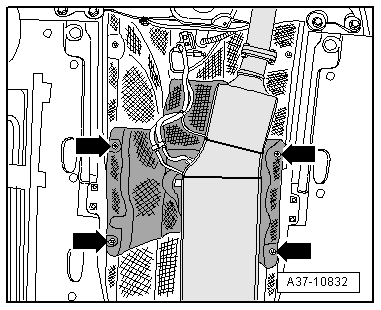
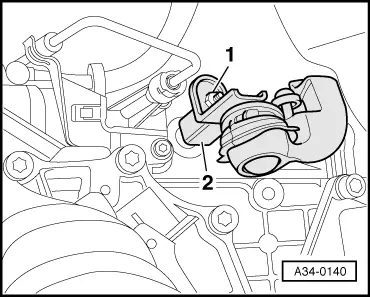
| Heat shield for drive shaft to gearbox | 23 |
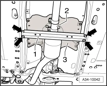
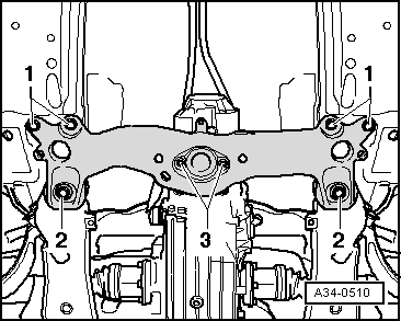
| Tunnel cross piece (front) to body | 55 |