
A4 Mk2
| Removing gearbox - vehicles with 8-cyl. MPI engine (Audi S4) |
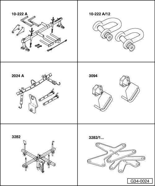
| Special tools and workshop equipment required |
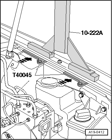
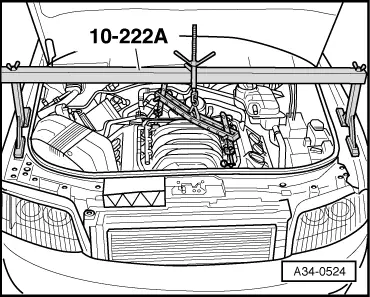
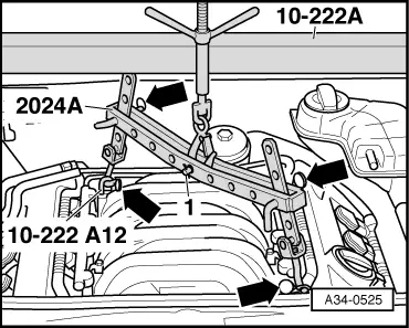
| t | Support bracket -10-222 A- |
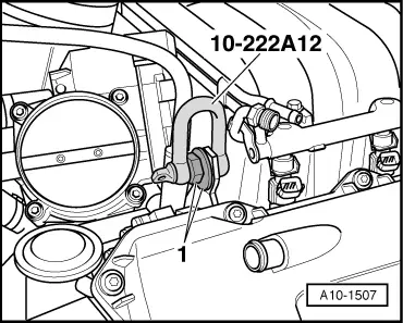
| t | Shackle -10-222 A /12- |
| t | Lifting tackle -2024 A- |
| t | Hose clamps, up to Ø 25 mm -3094- |
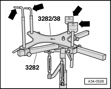
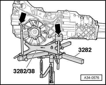
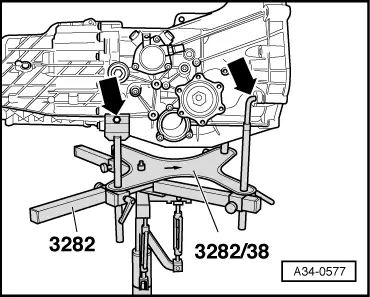
| t | Gearbox support -3282- |
| t | Adjustment plate -3282/38- |
|
|
|
|
|
|
 Note
Note
|
|
 Caution
|
|
|
|
|
|
|
|
|
|
|
|
|
|
|
|
|
|
Note
|
|
|
|
|
|
|
|
 WARNING
|
|
|
|
|

|
|
|
|
|
|
|
|
|
|
|
|
|
Note |
|
|
|
|
|
Note
|
|
Note
|
|
|
|
Note
|
|
|
|
Note
|
|
|
|
Note
|
|
|
|
|
|
|
|
|
|
|
|
|
|
|
|
|
|
Note
|
|
|
|
Note
|
|
Note
|
|
|

|