audi Workshop Repair Guides

Audi Workshop Service and Repair Manuals

Removing and installing selector lever cable on vehicles with 3.2 ltr. FSI engine with vehicle ID No. from 8E_8A 002700 onwards > < Exploded view - selector lever cable and locking cable on vehicles with vehicle ID No. from 8E_8A 002700 onwards
Removing and installing selector lever cable on vehicles with 2.0 ltr. TFSI engine with vehicle ID No. from 8E_8A 002700 onwards
Special tools and workshop equipment required
   
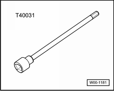
t  Socket and key -T40031-
Removing
–  Remove selector lever handle → Chapter.
–  Remove selector mechanism cover → Chapter.
–  Shift selector lever to position “D”.
  W00-1181
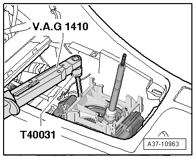
–  Insert socket and key -T40031- through access hole in selector mechanism and loosen clamping bolt at rear of selector lever cable approx. 1 turn.
  Note
t  Only loosen clamping bolt approx. one turn - do not remove.
t  Clamping bolt can only be accessed with selector lever in position “D”.
t  With clamping bolt loosened, selector lever must remain in position “D”.
–  Leave socket and key -T40031- in hole on selector mechanism.
  A37-10963
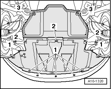
–  Open quick release fasteners -2- and -3- and take off rear noise insulation.
  A10-1320
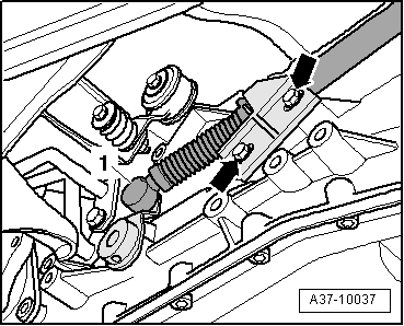
–  Pry ball socket -1- of selector lever cable off selector shaft lever.
–  Unscrew support bracket from gearbox -arrows-.
  Note
Shown in illustration with gearbox support removed.
  A37-10037
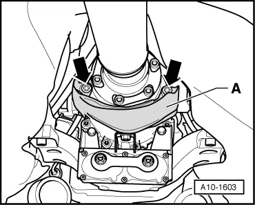
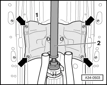
–  Unbolt heat shield -A- for propshaft -arrows-.
  A10-1603
–  Remove heat shield -1- for exhaust system below selector mechanism -arrows-.
–  Unscrew bolts at gearbox/propshaft flange.
–  Push propshaft -2- together towards rear final drive. The constant velocity joints can be moved axially.
  A34-0503
–  Tie propshaft up to side onto heat shield -arrow-.
–  If fitted, remove heat shield under selector mechanism → General body repairs, exterior; Rep. Gr.66.
  A34-0578
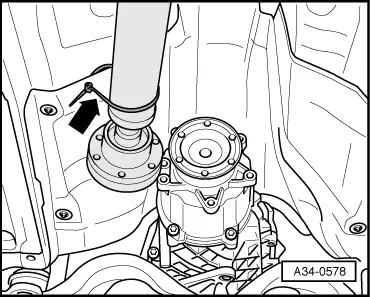
–  Pull off retaining clip -1- for selector lever cable from the side.
–  Pull selector lever cable -2- out of selector mechanism.
  Note
Do not bend or kink the selector lever cable.
Installing
Installation is carried out in reverse sequence; note the following:
l  Tightening torques → Chapter „Exploded view - selector lever cable and locking cable on vehicles with vehicle ID No. from 8E_8A 002700 onwards“
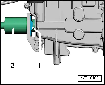
–  Make sure that the selector lever cable -1- has not been bent or kinked and that it is not under tension.
  A37-10402
l  Selector shaft lever -2- at gearbox must be in position “D”.
–  Carefully press selector lever cable -1- onto ball head of selector shaft lever -2-.
  Note
t  Make sure you do not bend the selector shaft lever when pressing on the cable, as this would make it impossible to obtain an accurate adjustment of the selector mechanism.
t  Do not bend or kink the selector lever cable.
t  Before installing, lightly grease cable eye and ball socket on selector lever cable with polycarbamide grease -G 052 142 A2-.
  A37-10964
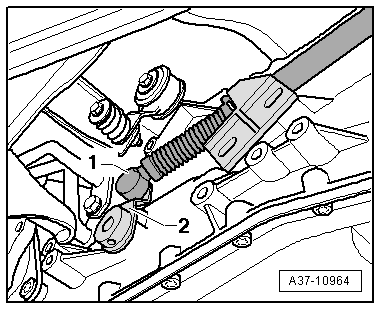
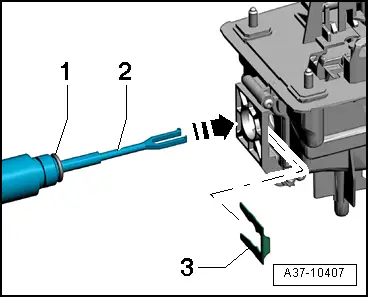
–  Renew O-ring -1- on selector lever cable.
–  Insert selector lever cable into selector mechanism -arrow-.
  A37-10407
–  Secure selector lever cable -2- to selector mechanism with a new retaining clip -1-.
l  Installation position: angled end of retaining clip must point towards selector mechanism.
  A37-10402
–  Secure support bracket for selector lever cable -arrows-.
–  Adjust selector lever cable → Chapter „Checking and adjusting selector lever cable on vehicles with vehicle ID No. from 8E_8A 002700 onwards“.
–  Bolt propshaft onto gearbox → Rear final drive 01R; Rep. Gr.39.
–  Install exhaust system so it is free of stress → Rep. Gr.26.
  A37-10037

Removing and installing selector lever cable on vehicles with 3.2 ltr. FSI engine with vehicle ID No. from 8E_8A 002700 onwards > < Exploded view - selector lever cable and locking cable on vehicles with vehicle ID No. from 8E_8A 002700 onwards