audi Workshop Repair Guides

Audi Workshop Service and Repair Manuals

Removing gearbox on vehicles with 4.2 ltr. MPI engine > < Removing gearbox on vehicles with 3.2 ltr. FSI engine
Installing gearbox on vehicles with 3.2 ltr. FSI engine
  Note
t  Use thread tap to remove any remaining locking fluid from all threaded holes which will accommodate self-locking bolts.
t  Renew self-locking nuts and bolts when performing assembly work.
t  Renew O-rings
t  Re-attach all cable ties at the same locations when re-installing.
   
–  Before installing gearbox, you must ensure that the torque converter is properly fitted in the gearbox.
l  If the torque converter is correctly installed, the depth between the contact surfaces at the tapped holes on the torque converter and the contact surface of the torque converter bellhousing is at least 19 mm.
  Caution
If the torque converter is not fitted correctly, the torque converter drive lugs or the ATF pump will be irreparably damaged when the gearbox is joined to the engine.
  V32-0069
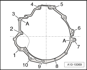
–  Before installing gearbox, check for correct positioning of dowel sleeves -A- at cylinder block. Install new dowel sleeves if necessary.
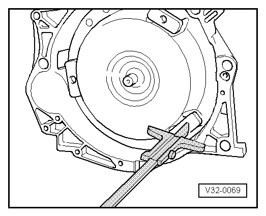
–  Install intermediate plate between engine and gearbox in the original position.
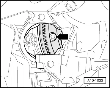
–  Before joining engine and gearbox, turn torque converter and drive plate (on engine) until one hole and one tapped hole are in line with the opening for the removed starter.
–  When pushing the engine and gearbox together, ensure that no wiring or pipes etc. can become trapped.
When you then install the gearbox, adhere to the following instructions.
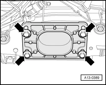
  Caution
Before and while you are tightening the bolts on the engine/gearbox flange keep checking that the torque converter can still be rotated behind the drive plate. If the converter cannot be turned, it must be assumed that it has not been installed correctly and the drive lugs on the converter or the ATF pump will be damaged when the bolts are fully tightened.
  A10-10069
–  Fit bolts -3- and -7- hand-tight.
–  Install gearbox support (right-side) with gearbox mounting → Chapter.
  A10-10069
–  Insert guide pin of adapter -T40058- so that the large diameter -arrow 1- faces engine. The smaller diameter -arrow 2- faces adapter.
  A13-10026
–  Counter-hold crankshaft using adapter -T40058- to secure torque converter bolts.
  Note
-Arrow- can be disregarded.
  A13-10022
–  Use new ribbed bolts to secure the torque converter to the drive plate. Use only the correct bolts (same as original equipment) → Electronic parts catalogue.
–  Screw in 3 bolts -arrow- for torque converter through opening for removed starter, and tighten lightly (turning crankshaft 1/3 turn each time).
–  Bolt gearbox onto engine.
  Note
t  Tightening torques apply only to lightly greased, oiled, phosphated or black-finished nuts and bolts.
t  Additional lubricant such as engine or gearbox oil may be used, but do not use graphite lubricant.
t  Do not use parts which have been degreased.
t  Tolerance for tightening torques ±15%.
  A10-1022
Engine/gearbox securing bolts
  A10-10069
ItemBoltNm
1M10x11565 → Note
2, 6M12x12565
3, 5M12x11065
4M12x11565
7M12x14065
8, 9, 10M10x8045
ADowel sleeves for centralising

1)  Property class 10.9
The remaining installation steps are carried out in reverse sequence; note the following:
–  Install starter → Electrical system; Rep. Gr.27.
–  Install anti-roll bar → Running gear, front-wheel drive and four-wheel drive; Rep. Gr.40.
–  Clean ATF pipes and ATF cooler → Chapter.
–  Secure ATF pipes to gearbox and engine → Chapter.
–  Install selector lever cable → Chapter.
–  Adjust selector lever cable → Chapter.
–  Install propshaft → Rear final drive 01R; Rep. Gr.39.
–  Install front exhaust pipes → Rep. Gr.26.
–  Align exhaust system so it is free of stress → Rep. Gr.26.
–  Install drive shafts → Running gear, front-wheel drive and four-wheel drive; Rep. Gr.40.
   
–  Allow stop for torque reaction support to settle under its own weight on rubber buffer for torque reaction support and tighten bolts -arrows-.
–  Follow steps required after connecting battery → Electrical system; Rep. Gr.27.
–  Check ATF level → Chapter.
  A13-0389
ComponentNm
Drive plate to torque converter85 → Note
Engine mounting to support23
Heat shield for drive shaft to gearbox23
Bracket for noise insulation to subframe10
Stop for torque reaction support to lock carrier28

2)  Renew bolts.
   

Removing gearbox on vehicles with 4.2 ltr. MPI engine > < Removing gearbox on vehicles with 3.2 ltr. FSI engine