
A4 Mk2
| Removing gearbox - vehicles with 6-cyl. 2.4 ltr. or 3.0 ltr. petrol engine (also for Audi Cabriolet) |

| Special tools and workshop equipment required |
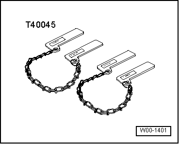
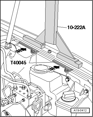
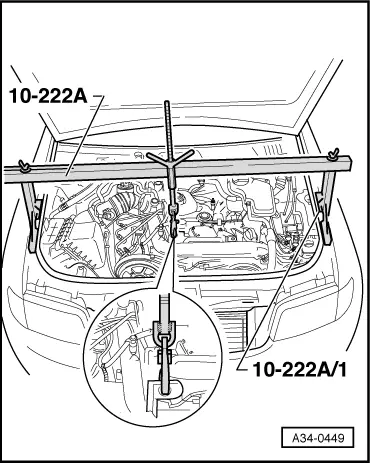
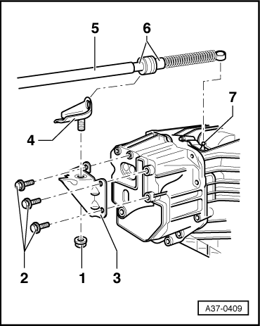
| t | Support bracket -10-222 A- |
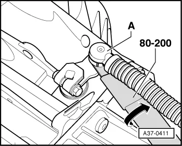
| t | Removal lever -80-200- |
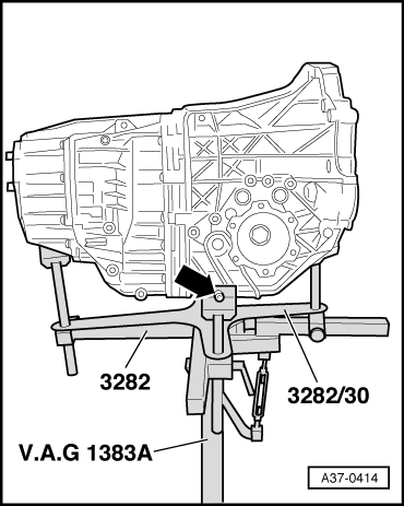
| t | Gearbox support -3282- |
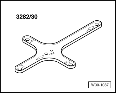
| t | Adjustment plate -3282/30- |
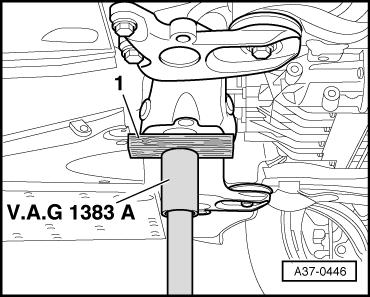
| t | Engine and gearbox jack -V.A.G 1383 A- |
|
|
 Note
Note
|
|
 Caution
|
|
|
|
|
|
|
|
|
|
|
|
|
|
Note
|

|
|
|
|
|
|
|
|
|
Note
|
|
|
|
Note
|
|
|
|
|
|
|
|
|
|
|
|
Note |
|
|
|
|
|
 WARNING
|
|
|
|
|
|
|
|
|
|
Note
|
|
|
|
Note
|
|
|
|
Note |
|
|
|
|
|
|
|
|
|
|
|
|
|
Note
|
|
|
|
Note
Note
|
|
|
|
|
|
|
|