| –
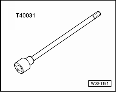
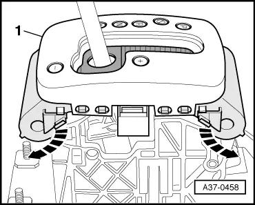
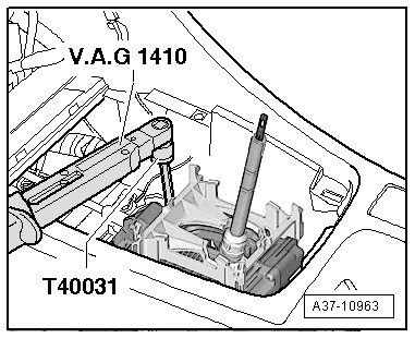
| Insert socket and key -T40031- through access hole in selector mechanism and loosen clamping bolt at rear of selector lever cable approx. 1 turn. |

Note | t
| Only loosen clamping bolt approx. one turn - do not remove. |
| t
| Clamping bolt can only be accessed with selector lever in position “D”. |
| t
| With clamping bolt loosened, selector lever must remain in position “D”. |
| –
| Leave socket and key -T40031- in hole on selector mechanism. |
| –
| Carefully move selector lever slightly forwards and backwards, without shifting lever into a different selector lever position. The selector lever cable is thereby slackened. |
| –
| Shift selector lever into tiptronic gate. |
Note | Do not touch selector lever again during adjustment process. |
| –
| Use socket and key -T40031- to tighten clamping bolt in this position, taking care not to touch selector lever. |
| –
| Install selector mechanism cover → Chapter. |
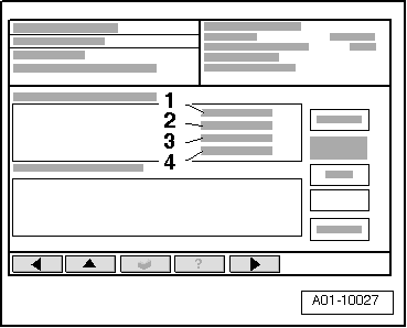
Note | Use a diagnostic tester, e.g. vehicle diagnostic, testing and information system -VAS 5051B- to compare the position of the multifunction switch -F125- with the position of the selector lever. |
|
|
|