| –
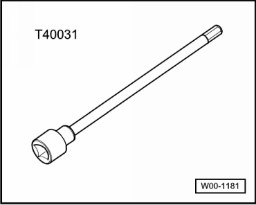
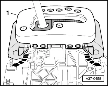
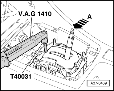
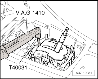
| Insert socket and key -T40031- through access hole in selector mechanism and loosen clamping bolt at rear of selector lever cable approx. 1 turn. |

Note | t
| Only loosen clamping bolt one turn - do not remove. |
| t
| Clamping bolt can only be accessed with selector lever in position “S”. |
| t
| The selector lever must remain in “S” position when clamping bolt is loosened; otherwise, adjustment will not be correct. |
| –
| Carefully move selector lever slightly forwards and backwards without shifting lever into a different selector lever position. |
| –
| Pull selector lever once more to the rear as far as possible into “S” position and release the selector lever. |
Note | Do not touch selector lever again during adjustment process. |
| –
| Use socket and key -T40031- to tighten clamping bolt in this position, taking care not to touch selector lever. |
| Vehicles with selector lever mechanism “PRND” and “PRNDS” |
| –
| Install selector mechanism cover → Chapter. |
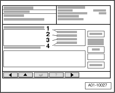
Note | Use a diagnostic tester, e.g. vehicle diagnostic, testing and information system -VAS 5051B-, to compare the position of the multifunction switch -F125- with the position of the selector lever. |
|
|
|