
A4 Mk2
| Electrical/electronic components and fitting locations |

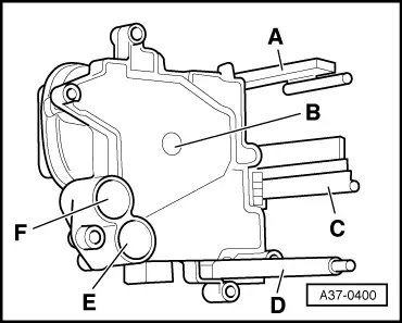
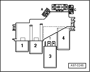
| 1 - | Control unit for automatic gearbox -J217- |
| q | Fitting location → Fig. |
| q | Control unit is checked by self-diagnosis |
| q | Removing and installing → Chapter |
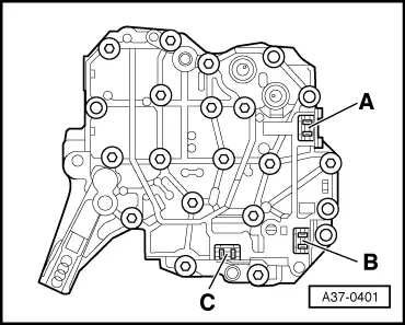
| 2 - | Hydraulic control unit |
| q | Fitting location → Fig. |
| q | Valves are checked via self-diagnosis. |
| q | Removing and installing → Chapter |
| 3 - | Selector mechanism cover |
| q | Removing and installing → Chapter |
| 4 - | tiptronic switch -F189- |
| q | Fitting location: integrated in printed circuit located in selector mechanism cover |
| q | Consists of 3 Hall sensors actuated by a magnet on the transverse slide of the sliding cover. |
| q | If malfunctions occur in the tiptronic switch -F189-, first check that the magnet on the transverse slide of the sliding cover is secured properly. If necessary, renew sliding cover. The printed circuit should only be renewed after the wiring has been checked. |
| q | Removing and installing → Chapter |
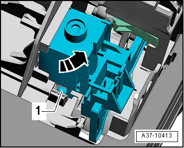
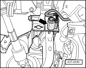
| 5 - | Selector lever lock solenoid -N110- |
| q | Fitting location → Fig. |
| q | Removing and installing → Chapter |
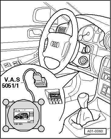
| 6 - | Diagnostic connector |
| q | Fitting location → Fig. |
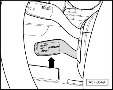
| 7 - | Cruise control system switch -E45- |
| q | Fitting location → Fig. |
| q | Removing and installing → Rep. Gr.94 |
| 8 - | Starter inhibitor relay -J207- |
| q | Fitting location → Fig. |
| 9 - | Voltage supply relay, terminal 30 -J317- |
| q | Fitting location → Fig. |
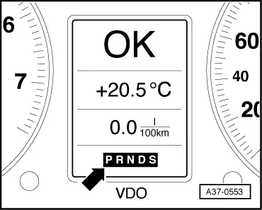
| 10 - | Selector lever position display -Y6- |
| q | Fitting location → Fig. |
| q | A fully illuminated gear selection indicator indicates a simple fault |
| q | A flashing gear selection indicator indicates a critical fault |
| q | A blank display indicates defective wiring or a defective selector lever position display -Y6-. |
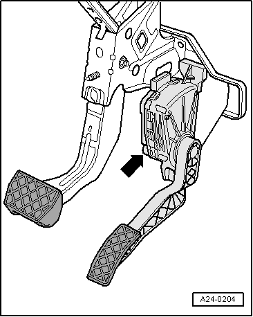
| 11 - | Kick-down switch -F8- |
| q | Not fitted as a separate component: on vehicles with petrol engine this function is performed by accelerator pedal position sender -G79- and accelerator pedal position sender 2 -G185-. The two senders are integrated in the accelerator pedal module; fitting location → Fig. |
| q | On vehicles with diesel engine the kick-down switch is incorporated in accelerator pedal position sender -G79- located in accelerator pedal module; fitting location → Fig. |
| q | Signal recognition in engine control unit, signal transmission from engine control unit to gearbox control unit via CAN bus |
| q | Removing and installing accelerator pedal module → Rep. Gr.20 |
| 12 - | Brake light switch -F- |
| q | Fitting location → Fig. |
| q | Signal recognition in engine control unit, signal transmission from engine control unit to gearbox control unit via CAN bus |
| q | Removing and installing → Brake system; Rep. Gr.46 |
|
|
 Note
Note
|
|
|
|
|
|
|
|
Note
|
|
Note
|
|
Note
|
|