
A4 Mk2
|
|
|
 Note
Note
|
|
Note
|
|
Note
|
|
Note
|
|
|
|
|
|
Note
|
|
|
|
Note
|
|
| Example: | ||
| Inserted shim “S3*” | 1.00 mm | |
| + | Dimension “e” | 0.33 mm |
| - | Measured value (in red scale) | 0.43 mm |
| = | Thickness of shim “S3” | 0.90 mm |
|
| Shim thickness (mm) → Note | ||
| 0.55 | 0.75 | 0.95 |
| 0.60 | 0.80 | 1.00 |
| 0.65 | 0.85 | 1.05 |
| 0.70 | 0.90 | |
Note
|
|
|
|
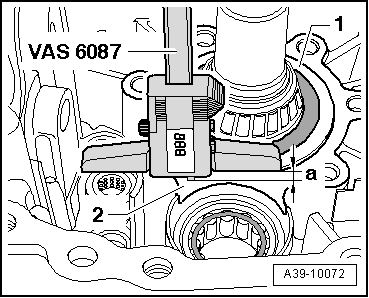
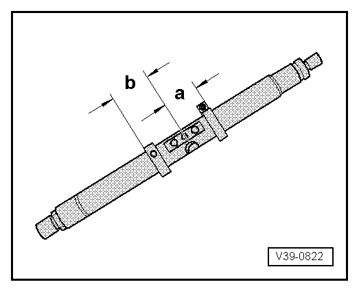
| Gap -a- | Shim “S4” → Note |
| Measured value (mm) | Thickness (mm) |
| 0.67 … 0.71 0.72 … 0.76 0.77 … 0.81 | 0.50 0.55 0.60 |
| 0.82 … 0.86 0.87 … 0.91 0.92 … 0.96 | 0.65 0.70 0.75 |
| 0.97 … 1.01 1.02 … 1.06 1.07 … 1.11 | 0.80 0.85 0.90 |
| 1.12 … 1.16 1.17 …1.21 1.22 … 1.26 | 0.95 1.00 1.05 |
| 1.27 … 1.31 1.32 … 1.36 1.37 … 1.41 | 1.10 1.15 1.20 |
| 1.42 … 1.46 1.47 … 1.51 1.52 … 1.56 | 1.25 1.30 1.35 |
| 1.57 … 1.61 | 1.40 |
Note
|
|
|
Note
|
|