
A4 Mk2
|
 WARNING
 Note
Note
|
|
|
|
 Caution
|
|
|
|
|
|
|
|
|
|
|
|
|
|
|
|
|
|
|
|
|
|
|
|
|
|
Note
|
|
Note
|
|
|
|
|
|
|
|
|
|
|
|
|
|
|
|
|
|
|
|
|
|
|
|
|
|
|
|
|
|
|
|
|
|
|
|
|
|
|
|
|
|
|
|
|
|
|
|
|
|
|
|
Note
|
|
|
|
Note
|
|
|
|
|
|
|
|
|
|
|
|
|
|
Note
|
|
|
|
Note
|
|
|
|
|
|
Note
|
|
|
|
|
|
|
|
|
|
|
|
|
|
|
|
|
|
|
|
|
|
|
|
|
|
|
|
|
|
Note
|
|
Note
|
|
|
|
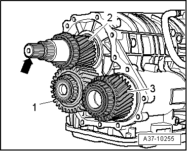
| Available shims - Thickness of shims in mm | ||
| 1.6 | 2.0 | 2.4 |
| 1.8 | 2.2 | 2.6 |
|
|
|
|
|
|
|
Note
|
|
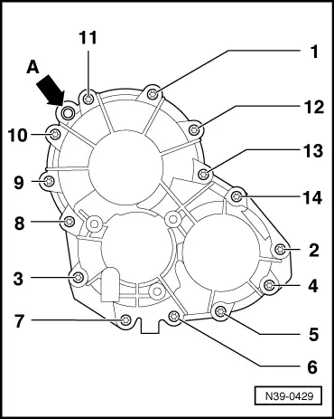
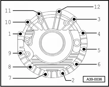
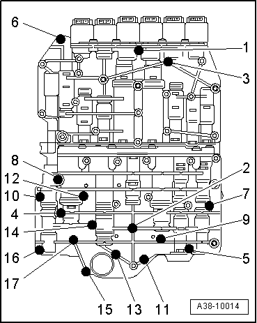
| Step | Tightening sequence | ||
| I |
| ||
| II |
|
|
|
|
|
|
|
|
|
Note |
|
|
|
Note
|
|
Note
|
|
|
|
|
|
|
|
|
|
|
|
| Step | Tightening sequence | ||
| I |
| ||
| II |
|
|
|
|
|
|
|
Note
|
|
| Step | Tightening sequence | ||
| I |
| ||
| II |
|
Note
|
|
|
|
|
|
Note
|
|
|
|
| Step | Tightening sequence | ||
| I |
| ||
| II |
|
Note
|
|
|
|
|
| Step | Tightening sequence | ||
| I |
| ||
| II |
|
|
|
|
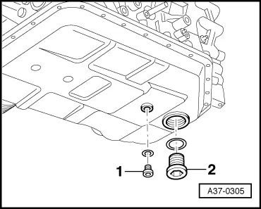
| Component | Nm |
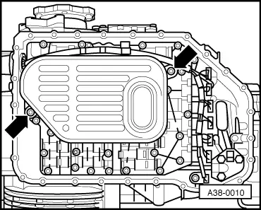
| ATF supply unit to gearbox housing | 10 |
| Valve body to gearbox housing | 8 |
| ATF strainer to valve body | 5 |
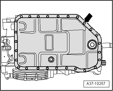
| ATF oil pan to gearbox housing | 10 |
| Bearing bracket for flange shaft (left-side) to gearbox | 23 |
| Cover for final drive to gearbox | 23 |
| Flange shaft (right-side) | 25 |
| Cover for front axle drive / intermediate flange for front axle drive to gearbox | 23 |
| Transfer box housing to gearbox | 23 |