audi Workshop Repair Guides

Audi Workshop Service and Repair Manuals

Removing and installing ATF pump in housing of ATF supply unit > < ATF supply unit - exploded view of components
Removing and installing complete ATF supply unit (gearbox not dismantled)
Removing
l  Gearbox mounted on assembly stand → Chapter.
–  Place used oil collection and extraction unit -V.A.G 1782- below gearbox.
   
  WARNING
Wear safety goggles.
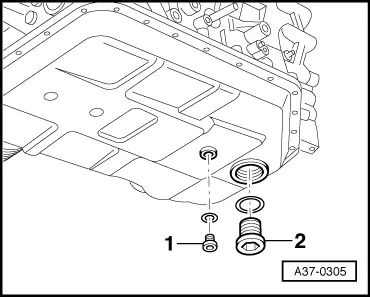
–  Remove ATF drain plug -1- and allow ATF to drain off.
  Note
t  Observe relevant disposal regulations.
t  Some ATF always remains in the oil pan.
–  Remove torque converter.
  A37-0305
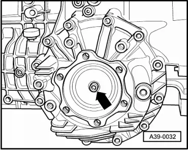
–  Remove bolt -arrow- securing flange shaft (right-side). To do so, screw two bolts into flange and counterhold flange shaft with suitable lever.
–  Place used oil collection and extraction unit -V.A.G 1782- below gearbox.
–  Pull out flange shaft (right-side).
  A39-0032
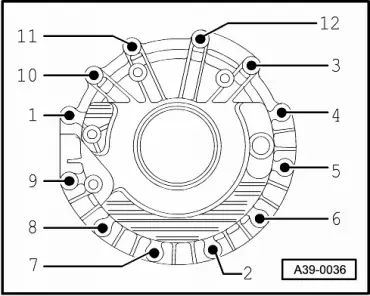
–  Slacken bolts on housing cover for final drive in the sequence -12 ... 1- and remove bolts.
  Caution
t  Detach cover for final drive from gearbox housing slowly and carefully. The differential may otherwise fall out of the gearbox.
t  A differential which has fallen to the ground can no longer be installed. If this happens, the gearbox must be renewed.
–  Remove cover for final drive.
  Caution
t  Take care that the outer race for the tapered roller bearing or the shim for the differential does not fall out of the final drive cover.
t  The outer race for the tapered roller bearing must be re-installed in the same position.
t  Thickness of shim has been measured to fit; the shim must not be replaced with another shim of different thickness.
  A39-0036
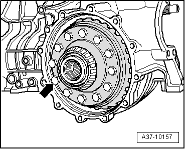
–  Carefully take out differential -arrow-.
  A37-10157
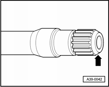
–  Cover splines on flange shaft (left-side) -arrow- with insulating tape to prevent damage to twin-lip oil seal for final drive/gearbox housing when pulling off flange shaft (left-side). Take care to cover the splines completely, without creasing or overlapping the tape.
  A39-0042
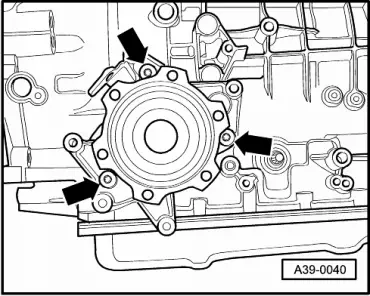
–  Unbolt bearing bracket for flange shaft (left-side) -arrows-.
–  Pull out flange shaft (left-side).
  Note
While pulling out the flange shaft (left-side), it must be guided carefully by hand to avoid damaging the twin-lip oil seal between the final drive and gearbox housing.
  A39-0040
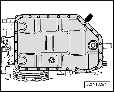
–  Loosen bolts for ATF oil pan -arrow- in diagonal sequence and remove bolts.
–  Take off ATF oil pan.
  A37-10257
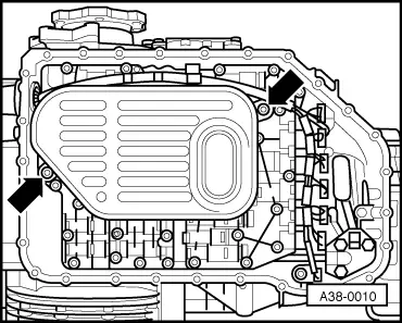
–  Remove bolts -arrows- for ATF strainer.
–  Detach ATF strainer from valve body.
  A38-0010
–  Remove retaining clip -arrow- for wiring harness connector.
–  Remove wiring harness connector by pressing inwards.
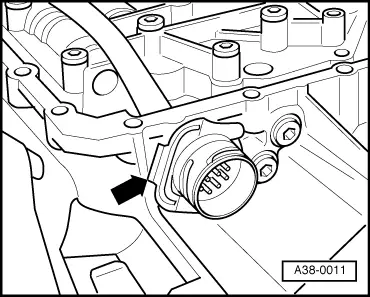
  A38-0011
–  Unscrew bolt -arrow- and detach gearbox speed sender -G38-/gearbox output speed (sender) -G195-.
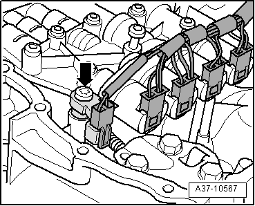
  A37-10567
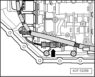
–  On gearboxes with hydraulic control type “E18/2”, detach electrical connector for gearbox input speed sender -G182- at valve body -arrow- and unplug connector.
  A37-10258
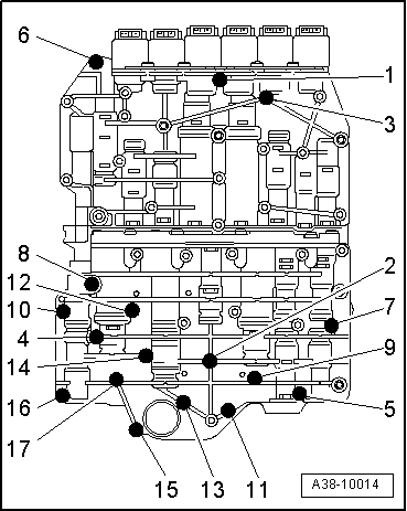
–  Slacken bolts for valve body in the sequence -17 ... 1- and remove bolts.
  Caution
t  Only remove the bolts marked; bolt -6- is only fitted on gearboxes with hydraulic control type “E17”.
t  If other bolts are removed, this may affect the operation of the valve body or the valve body could come apart.
t  Observe different bolt lengths.
  A38-10014
–  Detach valve body carefully from gearbox.
  Caution
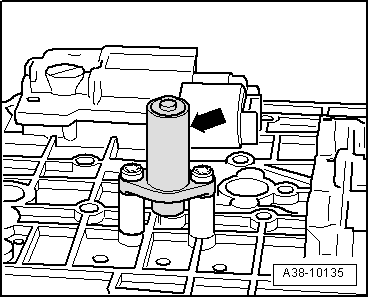
Only on gearboxes with hydraulic control type “E17”: To prevent damage after removal, do not put down the valve body on the gearbox input speed sender -G182- (located on reverse side of valve body -arrow-).
  A38-10135
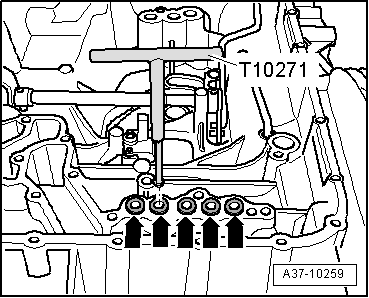
–  Using extractor tool -T10271-, pull out sealing sleeves -arrows- from feed bores to clutches “C”, “A”, “B” and “E” and to torque converter lock-up clutch.
  A37-10259
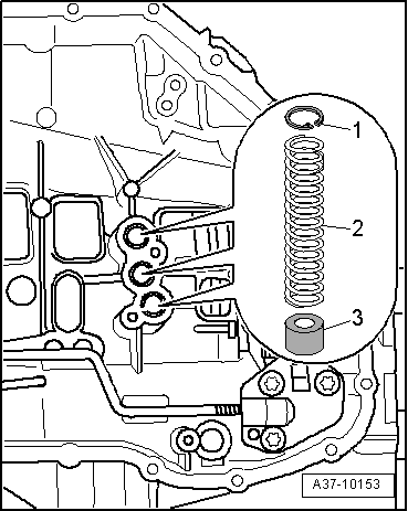
–  Remove 3 circlips -1-.
–  Detach coil springs -2-.
–  Pull out sealing sleeves -3- using extractor tool -T10271-.
  A37-10153
–  Turn gearbox on assembly stand.
l  ATF supply unit points upwards.
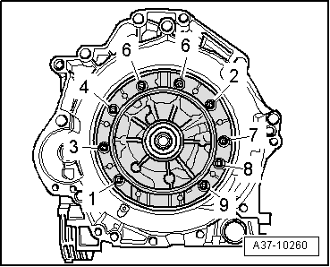
–  Slacken bolts for ATF supply unit in the sequence -9 ... 1- and remove bolts.
–  Remove bolts with washers.
  A37-10260
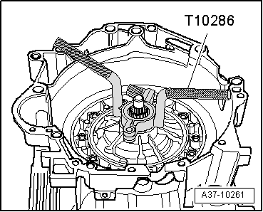
–  Attach puller for ATF supply unit -T10286- to stator shaft and lift out ATF supply unit by pulling firmly.
  A37-10261
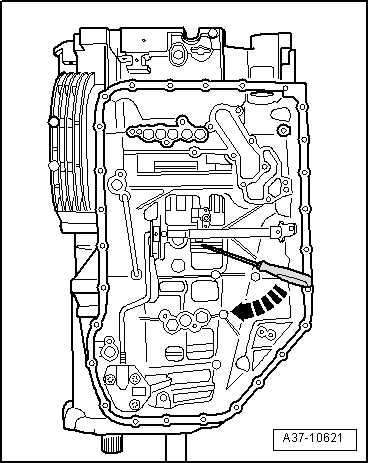
If it is not possible to detach ATF supply unit:
–  Insert a screwdriver between sun gear “I” and flanged housing on underside of gearbox and lever components located above sun gear upwards -arrow-.
  A37-10621
Installing
–  Make sure that body “II” is still correctly installed.
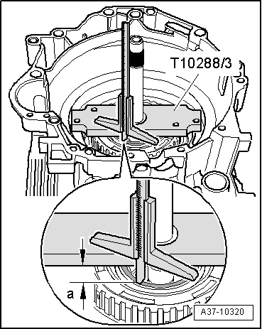
–  Measure distance between seat for shim on body “II” and contact surface for ATF pump on gearbox housing.
l  Dimension -a- = 6.0 mm (minimum).
l  The shim must not be fitted at this stage.
If dimension -a- is exceeded, body “II” was pulled out of plates upon removal.
–  Remove body “II” and then install again → Anchor.
  A37-10320
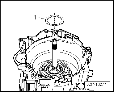
–  Fit existing shim -1- onto plate carrier “C”.
  A37-10277
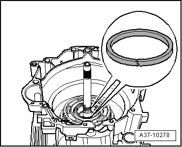
–  Renew two rectangular section seals on input shaft.
–  Lightly lubricate the two rectangular section seals on the input shaft with vaseline before fitting. Use vaseline only. Other types of lubricant will cause the gearbox hydraulics to malfunction.
–  Make sure that rectangular section seals are seated properly all round in groove on input shaft.
  A37-10278
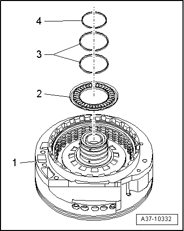
–  Lightly lubricate reverse side of axial needle bearing -2- with vaseline. Use vaseline only. Other types of lubricant will cause the gearbox hydraulics to malfunction.
–  Fit axial needle bearing onto ATF supply unit -1- so that it sticks in position.
l  Closed side of axial needle bearing faces ATF supply unit.
–  Renew rectangular section seals -3- and -4- on stator shaft.
–  Lightly lubricate the rectangular section seals with vaseline before fitting. Use vaseline only. Other types of lubricant will cause the gearbox hydraulics to malfunction.
–  Make sure that rectangular section seals are seated properly all round in grooves on stator shaft.
  A37-10332
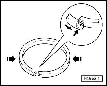
–  After installation, hook the ends of the rectangular section seals -arrows- together as illustrated.
  N38-0013
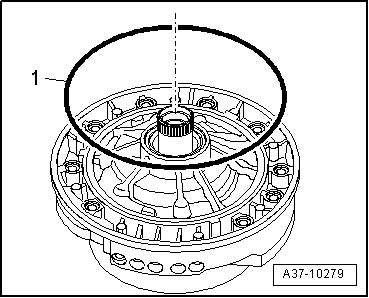
–  Renew O-ring -1- on ATF supply unit.
–  Lightly lubricate O-ring with vaseline. Use vaseline only. Other types of lubricant will cause the gearbox hydraulics to malfunction.
  A37-10279
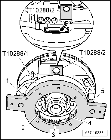
–  Align friction plates -3- of clutch “C” symmetrically using centring tool -T10288/1- (engage aligning pins -2- and -4- in splines of all friction plates).
–  Align friction plates in relation to housing of ATF supply unit (insert aligning pins -1- and -5- in corresponding drillings in ATF supply unit).
l  The aligning pins only fit in one position.
–  Hold centring tool in this position and insert wedge -T10288/2- at the side between corrugated spring and piston “F”-arrow-.
l  The wedge should hold all the plates in their present position.
–  Take off centring tool -T10288/1-; wedge -T10288/2- remains in position.
  A37-10333
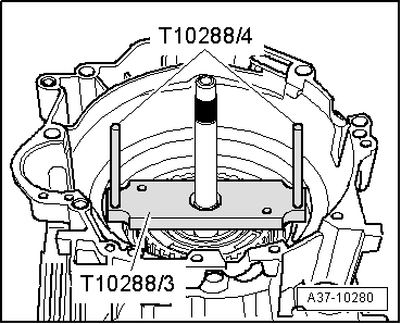
–  Align plate carrier for clutch “C” using centring tool -T10288/3- (screw guide pins -T10288/4- into gearbox housing).
l  The drillings in the centring tool and gearbox housing can only be aligned in one position.
–  Carefully lift off centring tool -T10288/3-; guide pins -T10288/4- remain in gearbox housing.
l  The plate carrier for clutch “C” must not be turned from this point onwards.
  A37-10280
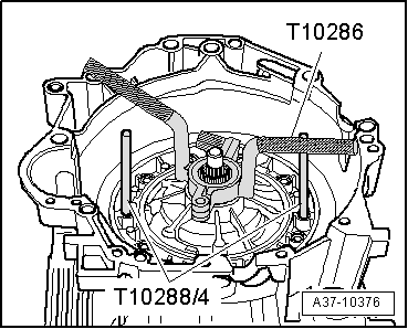
–  Apply puller for ATF supply unit -T10286- to stator shaft.
–  Bring ATF supply unit into installation position.
l  The recess for the flange shaft faces towards valve body side.
–  Fit corresponding holes on ATF supply unit onto guide pins -T10288/4-.
–  Install ATF supply unit carefully into gearbox housing and press down firmly.
–  Pull down ATF supply unit into its final position by alternately tightening two opposite securing bolts.
  A37-10376
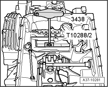
–  Pull out wedge -10288/2- with hook -3438-.
–  Detach puller for ATF supply unit -T10286-.
–  Unscrew guide pins -T10288/4-.
  A37-10281
–  Fit bolts for ATF supply unit with new washers into ATF supply unit housing.
–  Secure bolts for ATF supply unit in sequence -1 ... 9-.
l  Tightening torque: 10 Nm.
  Note
Check that the ATF supply unit is correctly installed: it should be possible to turn the input shaft, otherwise the topmost plate of clutch “C” may have become trapped and bent on installation. If it is not possible to turn input shaft, remove ATF supply unit again and check plates for damage.
  A37-10260
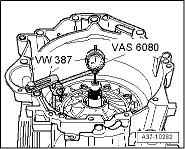
–  Set up dial gauge -VAS 6080- with universal dial gauge bracket -VW 387- on gearbox flange.
–  Apply dial gauge -VAS 6080- with dial gauge extension to gearbox input shaft as shown in illustration.
–  Set dial gauge to “0”.
–  Wrap insulating tape around input shaft to prevent damage.
–  Move input shaft up and down with pliers (avoid diagonal movements).
–  Read off axial clearance of input shaft from dial gauge.
l  Specification: 0.10 ... 0.30 mm
  Note
If no axial clearance can be measured (0 mm), it is possible that the flange washers → Item and → Item have been interchanged.
If readout does not match specification:
–  Remove ATF supply unit again.
  A37-10282
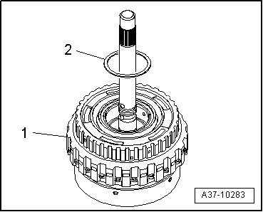
–  Determine correct thickness of shim -2- on body “II”, -item 1- according to following table.
l  If measured axial clearance is below specification: insert thinner shim of appropriate thickness.
l  If determined axial clearance is above specification: insert thicker shim of appropriate thickness.
  A37-10283
Available shims - Thickness of shims in mm
1.62.02.4
1.82.22.6

–  Install ATF supply unit again with new shim, new washers and new O-ring → Anchor.
–  Read off axial clearance of input shaft again → Anchor.
If reading again does not match specification:
–  Repeat adjustment.
If reading matches specification:
   
–  Turn gearbox on assembly stand.
l  Valve body side faces upwards.
–  Press sealing sleeves -3- into bores in gearbox housing as far as stop.
–  Fit coil springs -2- and secure with circlips -1- (push circlips down into bores as far as shoulder).
  A37-10153
  Caution
Only on gearboxes with hydraulic control type “E17”: To prevent damage after removal, do not put down the valve body on the gearbox input speed sender -G182- (located on reverse side of valve body -arrow-).
  A38-10135
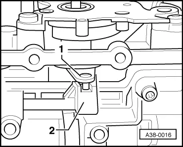
–  Place valve body in position on gearbox housing (do not apply force). At the same time insert pin of detent plate -1- so that it engages in slot on selector slide -2-.
  A38-0016
–  Fit bolts for valve body.
  Note
t  Note different bolt lengths.
t  Bolt -6- is only fitted on gearboxes with hydraulic control type “E17”.
t  On gearboxes with hydraulic control type “E18/2”, make sure that electrical wiring for gearbox input speed sender -G182- does not become trapped between gearbox housing and valve body.
–  Tighten bolts on valve body in two stages as follows:
  A38-10014
StepTightening sequence
I
–  Tighten bolts hand-tight in sequence -1 ... 17-.
II
–  Tighten bolts to 8 Nm in sequence -1 ... 17-.

   
–  Renew O-rings for wiring harness connector.
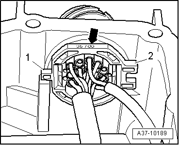
–  Fit wiring harness connector -arrow- in gearbox housing.
l  Installation position: lugs -1- and -2- on shoulder are horizontal, flat part -arrow- of connector should be parallel to sealing surface for ATF oil pan.
  A37-10189
–  Fit retaining clip -arrow- for wiring harness connector and check proper engagement.
  A38-0011
–  Secure gearbox speed sender -G38-/gearbox output speed sender -G195--arrow-.
l  Tightening torque: 10 Nm.
  A37-10567
–  On gearboxes with hydraulic control type “E18/2”, connect electrical wiring for gearbox input speed sender -G182-.
–  Clip electrical connector into retainer on valve body -arrow-.
  A37-10258
–  Renew ATF strainer.
–  Fit ATF strainer to valve body and secure -arrows-.
l  Tightening torque: 5 Nm.
  Note
  A38-0010
t  Clean magnets (6x) in ATF oil pan.
t  Ensure that magnets make full contact with ATF oil pan.
–  Install ATF oil pan -arrow- with new gasket.
–  Tighten bolts for ATF oil pan progressively in diagonal sequence.
l  Tightening torque: 10 Nm.
  A37-10257
–  Renew oil seal for flange shaft (left-side) if necessary → Automatic gearbox 01V, front-wheel drive and four-wheel drive; Rep. Gr.39.
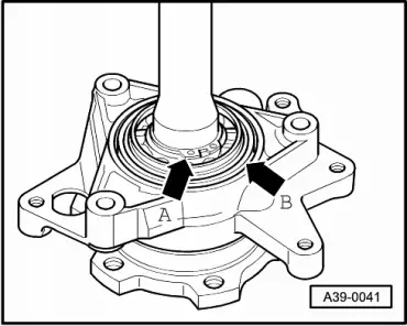
–  Renew O-ring -arrow B- in bearing bracket for flange shaft (left-side).
  Note
-Arrow A- can be disregarded.
–  Renew twin-lip oil seal for final drive/gearbox housing if necessary → Automatic gearbox 01V, front-wheel drive and four-wheel drive; Rep. Gr.39.
  A39-0041
–  Cover splines on flange shaft (left-side) -arrow- with insulating tape to prevent damage to twin-lip oil seal for final drive/gearbox housing when pushing in flange shaft. Take care to cover the splines completely, without creasing or overlapping the tape.
–  Insert flange shaft (left-side) into gearbox.
  Note
While pushing in the flange shaft (left-side), it must be guided carefully by hand to avoid damaging the twin-lip oil seal for final drive/gearbox housing.
  A39-0042
–  Tighten bearing bracket bolts for flange shaft (left-side) -arrows-.
l  Tightening torque: 23 Nm.
  Caution
t  Make sure that the outer race for tapered roller bearing and the shim for differential do not drop out of the final drive cover.
t  Make sure that outer race for tapered roller bearing is at previous position when installing.
t  Thickness of shim has been measured to fit; the shim must not be replaced with another shim of different thickness.
  A39-0040
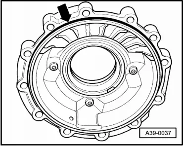
–  Renew O-ring -arrow- in cover for final drive.
–  Renew oil seal for flange shaft (right-side) if necessary → Automatic gearbox 01V, front-wheel drive and four-wheel drive; Rep. Gr.39.
  A39-0037
–  Install differential -arrow- carefully.
  A37-10157
–  Fit cover for final drive on gearbox housing.
–  Tighten bolts on cover for final drive in two stages as follows:
  A39-0036
StepTightening sequence
I
–  Tighten bolts hand-tight in sequence -1 ... 3-.
II
–  Tighten bolts to 23 Nm in sequence -1 ... 12-.

   
–  Tighten bolt -arrow- securing flange shaft (right-side). To do so, screw two bolts into flange and counterhold flange shaft with suitable lever.
l  Tightening torque: 23 Nm.
–  Detach gearbox from assembly stand.
  A39-0032
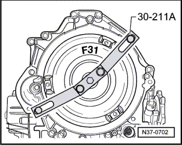
–  Place torque converter in position and secure against falling out using support bridge -30-211 A-.
–  Check position of torque converter → Automatic gearbox 01V, front-wheel drive and four-wheel drive; Rep. Gr.32.
–  Fill with ATF and check ATF level → Automatic gearbox 01V, front-wheel drive and four-wheel drive; Rep. Gr.37.
–  Fill front final drive with gear oil and check oil level → Automatic gearbox 01V, front-wheel drive and four-wheel drive; Rep. Gr.39.
–  Fill transfer gear housing with gear oil and check oil level → Automatic gearbox 01V, front-wheel drive and four-wheel drive; Rep. Gr.39.
Tightening torques
  N37-0702
ComponentNm
ATF supply unit to gearbox housing10
Valve body to gearbox housing8
ATF strainer to valve body5
ATF oil pan to gearbox housing10
Bearing bracket for flange shaft (left-side) to gearbox23
Cover for final drive to gearbox23
Flange shaft (right-side)25


Removing and installing ATF pump in housing of ATF supply unit > < ATF supply unit - exploded view of components