| –
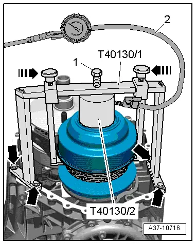
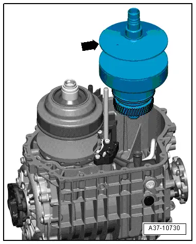
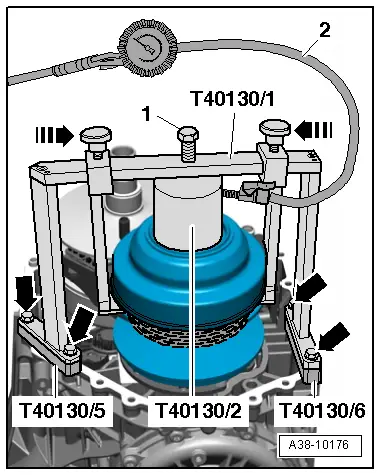
| Place adapter -T40130/2- on pulley set “II”. |
| l
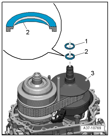
| Check for correct positioning of the O-rings in the adapter -T40130/2-. Both O-rings must be fitted. |
| l
| O-rings in adapter -T40130/2- and sealing surfaces on pulley set must be clean and coated with ATF. |
| –
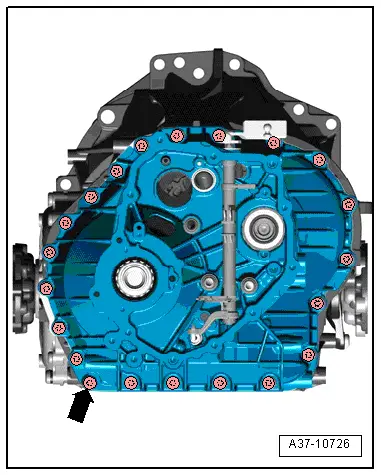
| Align support bracket -T40130/1- centrally on adapter -T40130/2- with spacers -T40130/5- and -T40130/6-, and bolt support bracket onto gearbox housing -bottom arrows-, as shown in illustration. |
| –
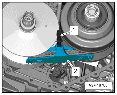
| Screw in bolt -1- until adapter -T40130/2- is pressed against pulley set “II”. |
| –
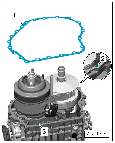
| Connect compressed air hose -2- for tyre valves to adapter -T40130/2- and apply approx. 3 bar. |
| l
| The pulley set should open and the chain should relax. |
| –
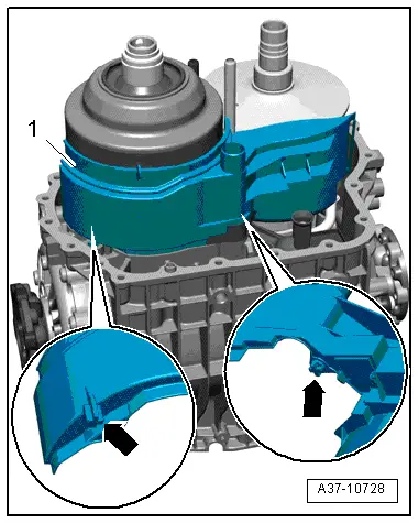
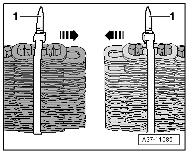
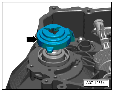
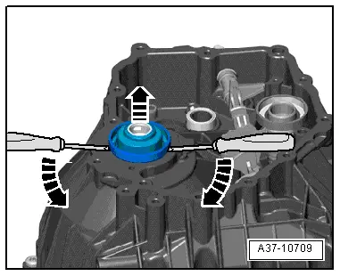
| Slide in the two arresters in the direction of the -arrows- to secure the top side of the pulley. |
| –
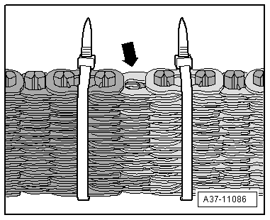
| Lock the arresters in this position using the knurled screws, taking care not to trap the chain. |
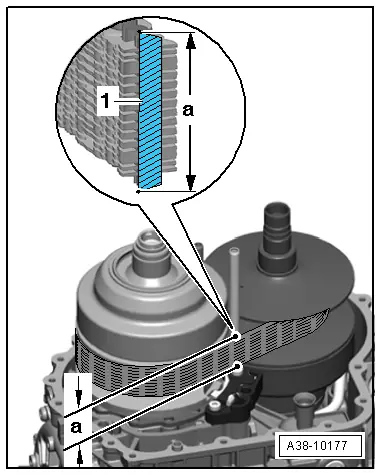
| Continued for gearboxes with any chain height: |
|
|
|

 Note
Note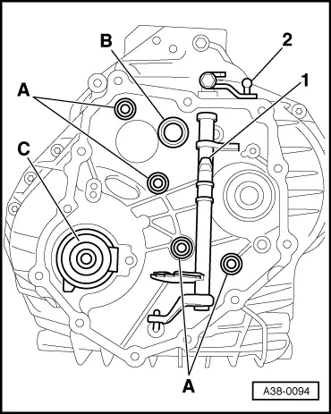
 Caution