
A4 Mk2
| Removing and installing sump and balance shaft assembly |

| Special tools and workshop equipment required |
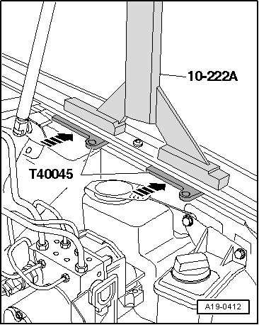
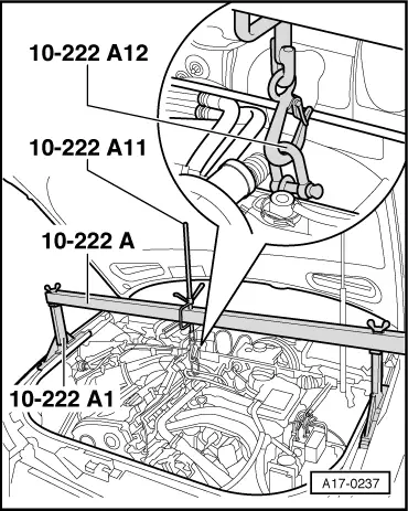
| t | Support bracket -10-222 A- |
| t | Shackle -10 - 222 A/12- |
| t | Used oil collection and extraction unit -V.A.G 1782- |
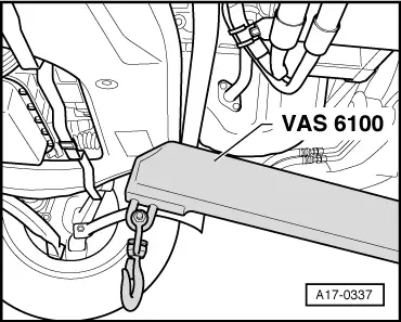
| t | Workshop hoist -VAS 6100- or workshop hoist -V.A.G 1202- |
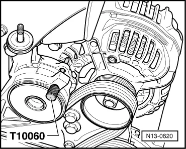
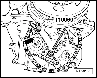
| t | Locking pin -T10060 A- or -T10060- |
| t | Mud wing compensation plate -T40045- |
| t | Electric drill with plastic brush attachment |
| t | Safety goggles |
| t | Sealant → Parts catalogue |
 Note
Note
|
|
|
Note |
|
|
|
|
|
|
|
|
|
|
|
|
|
|
|
|
|
|
|
|
|
|
|
|
|
Note
|
|
 WARNING
|
|
|
|
|
|
|
|
|
|
Note |
|
|
|
|
|
|
|
Note |
|
Note
|
|
|
|
|
|
|
|
|
|
|
|
|

|
|

|
Note
|
|
Note
|
|
Note
|
|
|
|
|
|
 Caution
Note
|
|
|
|
|
|
|
|
|
|
|
|
Note |
|
|
| Component | Nm | |||||
| Balance shaft assembly | 15 + 90° 1)2) | |||||
| Oil pump chain sprocket | 20 + 90° 1)2) | |||||
| Oil pipe to balance shaft assembly | 10 | |||||
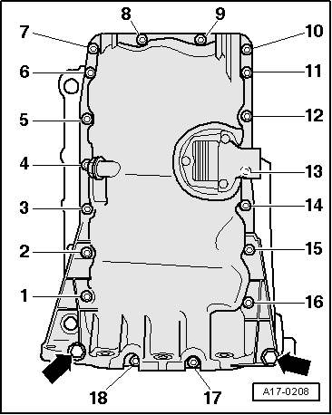
| Sump to cylinder block | M7 | 15 | ||||
| M10 | 40 | |||||
| Sump to gearbox | 45 | |||||
| Intake manifold support to sump | 23 | |||||
| Torque reaction support to sump | 23 | |||||
| Oil drain plug | 30 | |||||
| Engine mounting to console for engine mounting | 23 | |||||
| ||||||