
A4 Mk2
 Note
Note
|
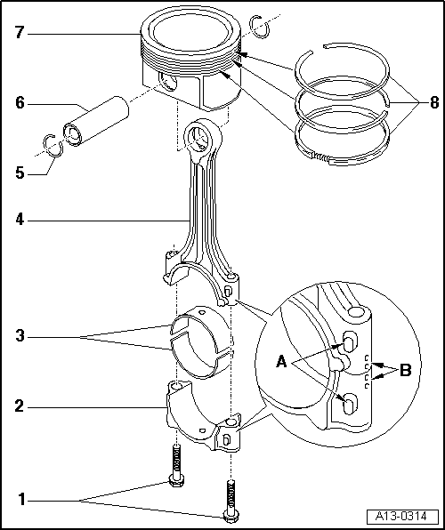
| 1 - | Conrod bolt, 30 Nm + 90° (1/4 turn) further |
| q | Renew |
| q | Lubricate threads and contact surface |
| q | Use old bolts when measuring radial clearance |
| q | To measure radial clearance, tighten to 30 Nm but do not turn further |
| 2 - | Conrod bearing cap |
| q | Mark cylinder number -B- |
| q | Installation position: Markings -A- face towards pulley end |
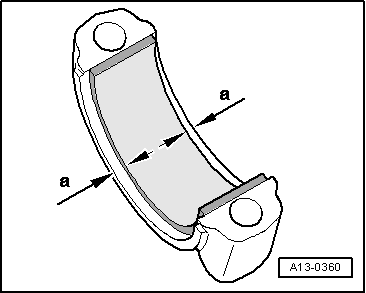
| 3 - | Bearing shells |
| q | Upper bearing shell with oil hole for piston pin lubrication |
| q | Installation position → Fig. |
| q | Do not interchange used bearing shells (mark positions) |
| q | Axial clearance (new): 0.10 ... 0.35 mm; wear limit: 0.40 mm |
| q | Check radial clearance with Plastigage: New: 0.01 ... 0.05 mm; Wear limit: 0.12 mm. Do not rotate crankshaft when checking radial clearance |
| 4 - | Conrod |
| q | Only renew as a complete set |
| q | Mark cylinder number -B- |
| q | Installation position: Markings -A- face towards pulley end |
| q | With oil drilling for piston pin lubrication |
| 5 - | Circlip |
| 6 - | Piston pin |
| q | If difficult to move, heat piston to approx. 60 °C |
| q | Remove and install using drift -VW 222 A- |
| 7 - | Piston |
| q | Checking → Fig. |
| q | Mark installation position and cylinder number |
| q | Arrow on piston crown points to pulley end |
| q | Install using piston ring clamp |
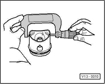
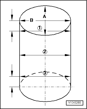
| q | Piston and cylinder dimensions → Chapter |
| q | Checking cylinder bore → Fig. |
| 8 - | Piston rings |
| q | Offset gaps by 120° |
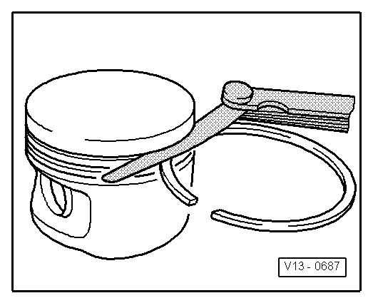
| q | Use piston ring pliers to remove and install |
| q | “TOP” must face towards piston crown |
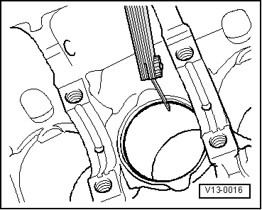
| q | Checking ring gap → Fig. |
| q | Checking ring-to-groove clearance → Fig. |
| Piston ring (in mm) | New | Wear limit |
| 1st compression ring | 0.20 … 0.40 | 0.8 |
| 2nd compression ring | 0.20 … 0.40 | 0.8 |
| Oil scraper ring | 0.25 … 0.50 | 0.8 |
|
|
| Piston ring (in mm) | New | Wear limit |
| 1st compression ring | 0.06 … 0.09 | 0.20 |
| 2nd compression ring | 0.05 … 0.08 | 0.20 |
| Oil scraper ring | 0.03 … 0.06 | 0.15 |
|
|
|
|
|
|
|
|