audi Workshop Repair Guides

Audi Workshop Service and Repair Manuals

Thermostat - exploded view > < Diagram of coolant hose connections
Draining and filling cooling system
   
Draining and filling cooling system
Special tools and workshop equipment required
t  Adapter for cooling system tester -V.A.G 1274/8-
t  Pipe -V.A.G 1274/10-
t  Drip tray for workshop hoist -VAS 6208-
t  Hose clip pliers -V.A.G 1921-
t  Cooling system charge unit -VAS 6096-
t  Refractometer -T10007-

Draining
  Note
Collect drained coolant in a clean container for re-use or disposal.
  WARNING
Hot steam/hot coolant can escape - risk of scalding.
t  The cooling system is under pressure when the engine is hot.
t  To allow pressure to dissipate, cover filler cap on coolant expansion tank with cloth and open carefully.
–  Open filler cap on coolant expansion tank
   
–  Vehicles with auxiliary heater: remove bolts -arrows- securing exhaust pipe for auxiliary/additional heater to noise insulation.
  A10-0407
–  Release quick-release fasteners -1- and -2- and take off front noise insulation.
  A10-1320
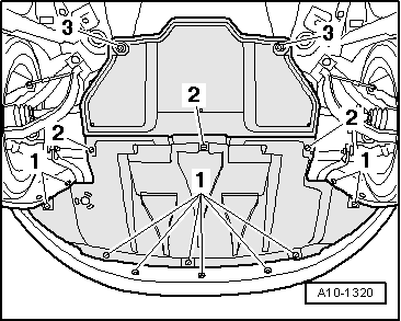
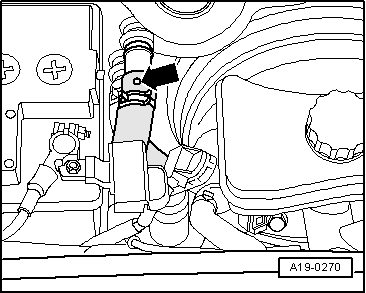
–  Place drip tray for workshop hoist -VAS 6208- or drip tray -V.A.G 1306- under engine.
–  Unscrew the drain plug -arrow- at coolant hose (bottom left) and drain off coolant.
Filling
  Note
t  
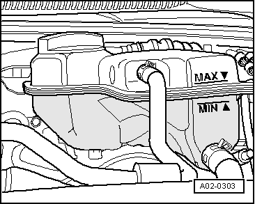
The cooling system is filled all year round with a mixture of water and radiator antifreeze/anti-corrosion agent.
t  Only use coolant additive G 12+ in accordance with TL -VW 774 F-. Other coolant additives could seriously impair in particular the anti-corrosion properties. The resulting damage could lead to loss of coolant and consequently to serious engine damage.
t  Coolant additive G12+ can be mixed with additives G11 and G12.
t  G 12+ and coolant additives marked "meeting specification TL -VW 774- F" prevent frost and corrosion damage as well as scaling. Such additives also raise the boiling point of the coolant. For these reasons the cooling system must be filled all year round with the correct antifreeze and anticorrosion additive.
t  Because of its high boiling point, the coolant improves engine reliability under heavy loads, particularly in countries with tropical climates.
t  Frost protection is required down to about –25 °C (in countries with arctic climate: down to about –35 °C).
t  The coolant concentration must not be reduced by adding water even in warmer seasons and in warmer countries. The antifreeze concentration must be at least 40 %.
t  If greater frost protection is required in very cold climates, the amount of G 12+ can be increased, but only up to 60 % (this gives frost protection to about -40 °C), as otherwise frost protection is reduced again, as is cooling effectiveness.
t  Use only clean tap water for mixing coolant.
t  If radiator, heat exchanger, cylinder head, cylinder head gasket or cylinder block are renewed, do not reuse old coolant.
t  Contaminated or dirty coolant must not be used again.
t  
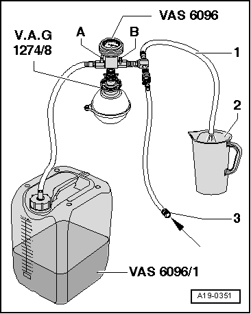
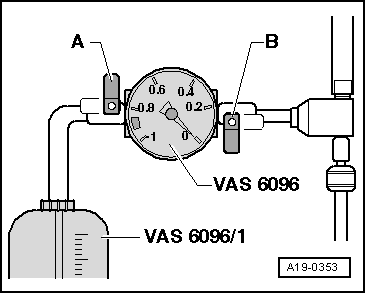
For checking anti-freeze protection in cooling system, use refractometer -T10007- for coolant additive G12+.
  A19-10111
–  Close drain plug -arrow-.
  A19-10111
–  Fill reservoir of cooling system charge unit -VAS 6096- with at least 8 litres of premixed coolant (based on recommended ratio):
t  G12+ (40%) and water (60%) for frost protection to –25 °C
t  G12+ (50%) and water (50%) for frost protection to –35 °C
t  G12+ (60%) and water (40%) for frost protection to –40°C
–  Screw adapter for cooling system tester -V.A.G 1274/8- onto coolant expansion tank.
–  Fit cooling system charge unit -VAS 6096- onto adapter for cooling system tester -V.A.G 1274/8-.
–  Run vent hose -1- into a small container -2-. (The vented air draws along a small amount of coolant, which should be collected.)
–  Close the two valves -A- and -B- (levers at right angles to direction of flow).
–  Connect hose -3- to compressed air.
l  Pressure: 6 ... 10 bar
  A19-0351
–  Open valve -B- (lever in direction of flow).
The suction jet pump generates a partial vacuum in the cooling system.
l  The needle on the gauge should move into the green zone.
–  Additionally open valve -A- briefly (lever in direction of flow) so that the hose of cooling system charge unit -VAS 6096- is filled with coolant.
–  Close valve -A- again.
–  Leave valve -B- open for another 2 minutes.
The suction jet pump will continue generating a vacuum in the cooling system.
l  The needle on the gauge should remain in the green zone.
–  Close valve -B-.
l  The needle on the gauge should stop in the green zone. The vacuum level in the cooling system is then sufficient for subsequent filling.
If the needle does not reach the green zone, repeat the process.
If the vacuum level drops, there is a leak in the cooling system.
–  Detach compressed air hose.
–  Open valve -A-.
The vacuum in the cooling system causes the coolant to be drawn out of the cooling system charge unit -VAS 6096-; the cooling system is then filled.
–  Detach cooling system charge unit -VAS 6096- from expansion tank.
  A19-0353
–  Fit pipe -V.A.G 1274/10- onto adapter for cooling system tester -V.A.G 1274/8-.
  A19-0065
–  Release coolant hose going to heat exchanger and pull back hose until bleeder hole in hose -arrow- is no longer blocked by the connection.
–  Top up the coolant until it emerges from the bleed hole in the coolant hose without bubbles.
–  Push coolant hose onto connection and secure with hose clip.
–  On vehicles with auxiliary heater, switch heater on (for about 30 seconds) and then off again.
–  Tighten filler cap on expansion tank.
–  Start engine.
–  Set heater/air conditioner on both sides to “HI”.
–  Run the engine for 3 minutes at 2000 rpm.
–  Allow the engine to run at idling speed until the two large coolant hoses at main radiator become warm.
–  Run the engine for 1 minute at 2000 rpm.
–  Switch off ignition and allow engine to cool down.
  A19-0270
–  Check coolant level.
l  The coolant level must be at the MAX marking when the engine is cold.
l  The coolant level can be above the MAX marking when the engine is warm.
  A02-0303

Thermostat - exploded view > < Diagram of coolant hose connections