
A4 Mk2
| Removing and installing camshafts and hydraulic chain tensioner |

| Special tools and workshop equipment required |
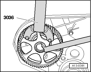
| t | Counterhold tool -3036- |
| t | Torque wrench -V.A.G 1331- |
| t | Torque wrench -V.A.G 1332- |
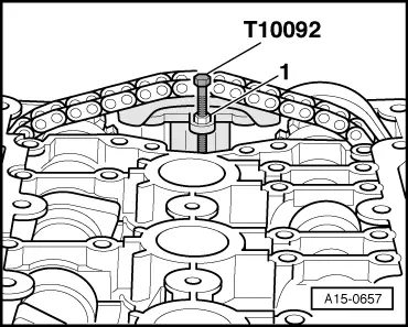
| t | Tensioning bolt -T10092- |
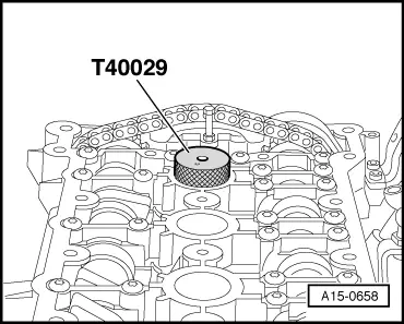
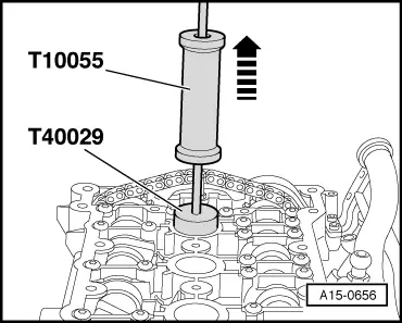
| t | Mandrel -T40029- |
| t | Puller -T10055- |
| t | Electric drill with plastic brush attachment |
| t | Safety goggles |
| t | Sealant → Parts catalogue |
 Note
Note
|
|
|
|
|
Note
|
|
Note
|
|
|
|
Note
|
|
|
|
|
Note
|
|
|
|
Note
|
|
 WARNING
|
|
Note
|
|
 Caution
|
|
|
Note
|
|
|
|
Note
|
|
Note
|
|
Note
|
|
|
|
Note
|
|
|
|
|
|
Note
|
|
|
|
| Component | Nm |
| Camshaft adjuster to camshaft | 100 |
| Hydraulic chain tensioner to cylinder head | 10 |
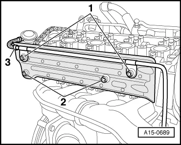
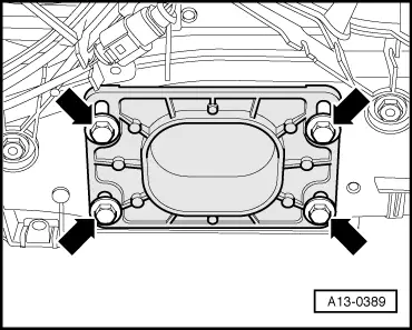
| Retaining frame to cylinder head | 8 |
| Camshaft sprocket to camshaft | 65 |
| Hall sender rotor to camshaft | 25 |
| Hall sender housing to cylinder head | 10 |
| Stop for torque reaction support to lock carrier | 28 |