
A4 Mk2
| Removing and installing sump |

| Special tools and workshop equipment required |
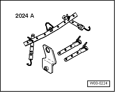
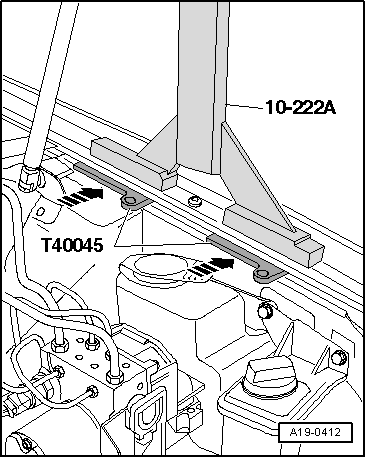
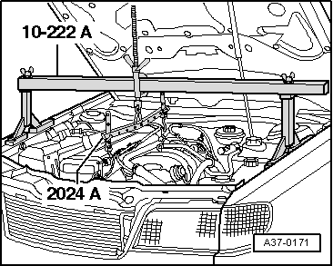
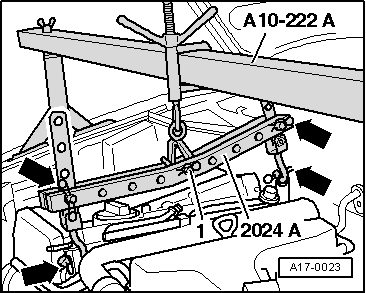
| t | Support bracket -10-222 A- |
| t | Socket -3249- or -T10058- |
| t | Used oil collection and extraction unit -V.A.G 1782- |
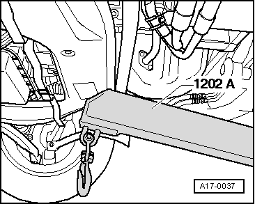
| t | Workshop crane -VAS 6100- or workshop crane -V.A.G 1202 A- |
| t | Mud wing compensation plate -T40045- |
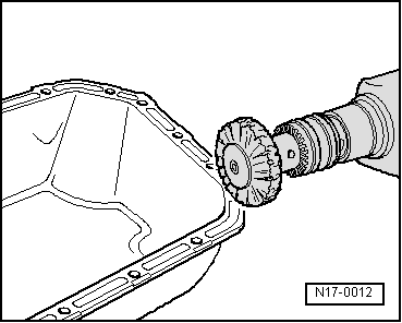
| t | Electric drill with plastic brush attachment |
| t | Safety goggles |
|
|
|
|
 Note
Note
|
|
|
|
Note |
|
|
|
|
|
|
|
|
|
 WARNING
|
|
|
|
|
|
|
|
|
|
Note
|
|
|
|
|
|
|
|
|
|
|
|
|
|
|
|
|
|
|
|
|
|
Note |
|
|
|
|
|
Note
|
|
Note |
|
|
|
| Component | Nm | |
| Sump to | M7 | 15 |
| cylinder block | M10 | 40 |
| Sump to gearbox | 45 | |
| Oil return pipe to sump | 10 | |
| Torque reaction support to sump | 23 | |
| Engine mounting to subframe | 23 | |
| Oil drain plug | 30 | |