audi Workshop Repair Guides

Audi Workshop Service and Repair Manuals

Enginecrankshaft group, pistons > < Securing engine to assembly stand
Installing engine
Installing engine
Installation is carried out in the reverse order; note the following:
  Note
t  Renew self-locking nuts and bolts when performing assembly work.
t  Renew bolts which are tightened to a specified angle as well as oil seals and gaskets.
t  Secure all hose connections with the correct type of hose clips (same as original equipment) → Parts catalogue.
t  Fit all cable ties in the original positions when installing.
Vehicles with manual gearbox:
–  Check clutch release bearing for wear; renew if necessary.
–  Lubricate splines of gearbox input shaft lightly with grease -G 000 100-. The guide sleeve for the release bearing should not be lubricated.
–  Check that the clutch plate is properly centralised (only necessary if you have carried out other work on the clutch).
–  Check clutch release bearing for wear; renew if necessary.
   
If the plastic ring for release bearing is loose:
–  Bond the plastic ring for release bearing to bearing race using adhesive -AMV 195 KD1 01-.
l  Three square lugs -arrows- on the plastic ring engage in the recesses in the bearing race.
l  The release bearing must be renewed if it has scoring deeper than 0.5 mm.
–  A needle bearing must be fitted in the crankshaft on vehicles with manual gearbox; install needle bearing if not already fitted → Chapter.
Vehicles with multitronic gearbox:
–  Clean input shaft splines and splines of damper unit on flywheel; remove corrosion and apply only a very thin coating of grease -G 000 100- to the splines. Remove any excess grease.
All vehicles:
–  Check whether dowel sleeves for centring the engine/gearbox assembly are fitted in the cylinder block; install dowel sleeves if necessary.
  N30-0285
–  Ensure that the intermediate plate is engaged on the sealing flange and pushed onto the dowel sleeves -arrows-.
–  Push intermediate plate between engine and gearbox onto dowel sleeves.
–  Attach engine to gearbox and screw in one bolt finger-tight.
–  Release spindles of support bracket -10-222 A-.
–  Lower engine, inserting studs of engine mountings into consoles for engine mountings as you do so.
  Note
t  Tightening torques apply only to lightly greased, oiled, phosphated or black-finished nuts and bolts.
t  Additional lubricant such as engine oil or gearbox oil may be used, but do not use lubricant containing graphite.
t  Do not use degreased parts.
t  Tolerance for tightening torques: ± 15%.
  A13-0682
Securing engine to manual gearbox
  A37-0075
ItemBoltNm
1, 4M12x7565
2M12x9065
3M12x7565 → Remark
5M12x11065 → Remark
6M12x11065
7 … 10M10x4545
11M12x13065
ADowel sleeves for centralising

1)  The wiring harness bracket is also secured with this bolt.
   
Securing engine to multitronic gearbox
  A37-10065
ItemBoltNm
1M12x9065 → Remark
2M10x6045 → Remark
3M12x6765 → Remark
4M12x7565 → Remark → Remark
5M12x7565 → Remark
6M12x11065 → Remark → Remark
7M12x8065 → Remark
8M10x5045 → Remark
9 … 11M10x4545 → Remark
ADowel sleeves for centralising

2)  Renew bolts.
3)  The wiring harness bracket is also secured with this bolt.
All vehicles:
Remaining installation steps are carried out in reverse sequence; note the following:
–  Install engine mountings free of stress. To do so, shake engine before tightening engine mountings.
–  Install exhaust system and align free of stress → Chapter.
–  Install air conditioner compressor → Air conditioning system; Rep. gr.87
–  Install power steering pump → Running gear, front-wheel drive and four-wheel drive; Rep. gr.48.
–  Install poly V-belt → Chapter.
   
–  Install lock carrier with attachments → General body repairs, exterior; Rep. gr.50.
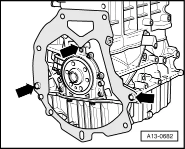
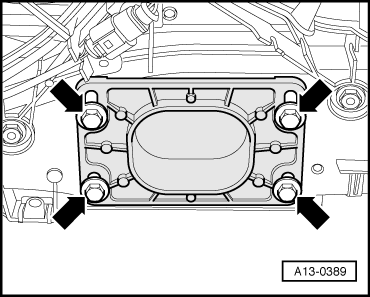
–  Allow stop for torque reaction support to rest on rubber buffer for torque reaction support under its own weight and tighten bolts -arrows-.
–  Install front bumper cover → General body repairs, exterior; Rep. gr.63.
–  Secure the ATF lines → multitronic gearbox 01J, front-wheel drive; Rep. gr.37.
–  Electrical connections and routing → Current flow diagrams, Electrical fault finding and Fitting locations.
–  Observe notes on procedures required after connecting battery → Electrical system; Rep. gr.27.
  Caution
Do not use a battery charger to boost starting. There is danger of damaging the vehicle's control units.
–  Check oil level → Chapter.
–  Fill cooling system → Anchor.
  Note
t  Drained-off coolant may only be used again if the original cylinder head and cylinder block are re-installed.
t  Contaminated or dirty coolant must not be used again.
–  Check power steering fluid level: → Running gear, front-wheel drive and four-wheel drive; Rep. gr.48.
–  Check ATF level → multitronic gearbox 01J, front-wheel drive; Rep. gr.37.
–  Check headlight adjustment → Booklet803.
Tightening torques
  Note
t  Tightening torques apply only to lightly greased, oiled, phosphated or black-finished nuts and bolts.
t  Additional lubricant such as engine oil or gearbox oil may be used, but do not use lubricant containing graphite.
t  Do not use degreased parts.
t  Tolerance for tightening torques: ± 15 %.
  A13-0389
ComponentNm
Bolts/nutsM69
 M715
 M820
 M1045
 M1265
Except for the following: 
Engine mounting to engine console23
Engine mounting to engine support23
Terminal B+ to starter16
Drive shaft heat shield to gearbox23
Fuel line to fuel rail22
Stop for torque reaction support to lock carrier28


Enginecrankshaft group, pistons > < Securing engine to assembly stand