
A4 Mk2
| Oil filter and oil cooler - exploded view of components |
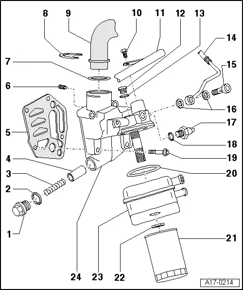
| 1 - | Screw plug, 40 Nm |
| 2 - | Seal |
| q | Renew |
| 3 - | Spring |
| q | For pressure relief valve, approx. 4 bar |
| 4 - | Piston |
| q | For pressure relief valve, approx. 4 bar |
| 5 - | Gasket |
| q | Renew |
| 6 - | Oil retention valve |
| q | Tighten to 8 Nm |
| q | Integrated into oil filter bracket |
| 7 - | O-ring |
| q | Renew |
| q | Slip on as far as collar of crankcase breather pipe → Item |
| 8 - | Retaining clip |
| 9 - | Crankcase breather pipe |
| 10 - | 20 Nm |
| q | Install using locking fluid; for locking fluid refer to → Parts catalogue |
| 11 - | Coolant pipe (bottom) |
| 12 - | Screw plug, 15 Nm |
| 13 - | Seal |
| q | If seal is leaking, cut open and renew |
| 14 - | Oil supply pipe |
| q | To turbocharger |
| 15 - | Banjo bolt, 30 Nm |
| 16 - | Seals |
| q | Renew |
| 17 - | Oil pressure switch -F1- |
| q | Opening/closing pressure 1.4 bar |
| q | Black insulation |
| q | Checking → Chapter |
| q | Tighten to 20 Nm |
| 18 - | Seal |
| 19 - | 15 Nm + 90° (1/4 turn) further |
| q | Renew |
| 20 - | Seal |
| q | Renew |
| q | Engage in lugs on oil cooler |
| 21 - | Oil filter |
| q | Observe change intervals → Booklet8E |
| q | Observe installation instructions on oil filter |
| q | Tighten to 20 Nm |
| 22 - | 25 Nm |
| 23 - | Oil cooler |
| q | See note → Chapter |
| q | Ensure clearance from surrounding components |
| q | Diagram of coolant hose connections → Chapter |
| 24 - | Oil filter bracket |
| q | With pressure relief valve, approx. 4 bar |
| q | Removing and installing → Chapter |