
A4 Mk2
| Connection diagram for charge pressure control and vacuum control - vehicles from 07.02 onwards |
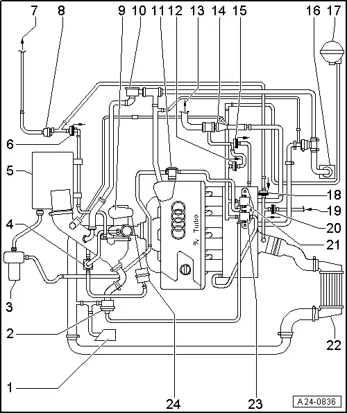
| 1 - | Resonator |
| 2 - | Mechanical air recirculation valve |
| q | Checking → Chapter |
| 3 - | Secondary air pump motor -V101- |
| 4 - | Charge pressure control solenoid valve -N75- |
| 5 - | Air cleaner |
| q | With air mass meter -G70- |
| 6 - | Non-return valve |
| q | Installation position: as shown in illustration, the arrow points in direction of flow |
| 7 - | To activated charcoal filter |
| 8 - | Activated charcoal filter solenoid valve 1 -N80- |
| 9 - | Turbocharger |
| 10 - | Pressure control valve for crankcase breather system |
| 11 - | Combination valve for secondary air system |
| 12 - | Non-return valve |
| q | Installation position: as shown in illustration, the arrow points in direction of flow |
| 13 - | To brake servo |
| 14 - | Vacuum booster |
| 15 - | Non-return valve |
| q | Installation position: as shown in illustration, the arrow points in direction of flow |
| 16 - | Crankcase breather |
| 17 - | Vacuum reservoir |
| 18 - | Non-return valve |
| q | Installation position: as shown in illustration, the arrow points in direction of flow |
| 19 - | To fuel system diagnostic pump -V144- |
| q | Only on USA vehicles |
| 20 - | Non-return valve |
| q | Installation position: as shown in illustration, the arrow points in direction of flow |
| 21 - | Secondary air inlet valve -N112- |
| q | Fitting location: below intake manifold |
| 22 - | Charge air cooler |
| q | With charge pressure sender -G31- |
| 23 - | Turbocharger air recirculation valve -N249- |
| q | Fitting location: below intake manifold |
| 24 - | Vacuum unit for charge pressure control |
| q | When the secondary air combination valve is opened, the mechanical charge pressure regulating valve in the turbocharger opens as well and the secondary air is delivered directly to the catalytic converter past the turbocharger |