audi Workshop Repair Guides

Audi Workshop Service and Repair Manuals

Checking valve guides > < Valve dimensions
Machining valve seats
  Note
If a good seating pattern cannot be obtained by grinding the valve seats (lapping), they must be refaced (machined):
Special tools and workshop equipment required
   
t  Depth gauge -VAS 6082-
t  
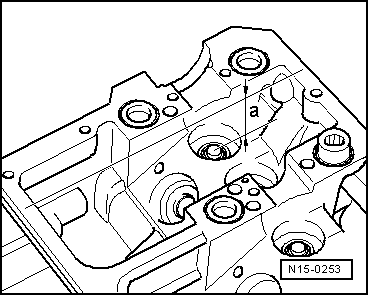
Valve seat machining tool
  Note
t  When servicing engines with leaking valves, it is not sufficient to machine (reface) the valve seats and renew the valves. The valve guides must also be checked for wear. This is particularly important on high-mileage engines → Chapter.
t  
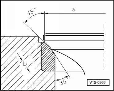
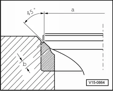
Valve seats should only be machined to the extent required to give a proper seating pattern.
t  The maximum permissible machining dimension must be calculated before starting work.
t  If the machining dimension is exceeded, the function of the hydraulic valve clearance compensation can no longer be ensured and the cylinder head must be renewed.
  W00-10210
Calculating maximum permissible machining dimension
–  Insert valve and press firmly against valve seat.
  Note
If the valve has to be renewed as part of a repair, use a new valve for the measurement.
–  Measure distance -a- between end of valve stem and top surface of cylinder head using depth gauge -VAS 6082-.
–  Calculate the maximum permissible machining dimension using the measured distance and the minimum dimension.
l  Minimum dimension for inlet valve: 43.4 mm.
l  Minimum dimension for exhaust valve: 43.2 mm.
Measured distance minus minimum dimension = max. permissible machining dimension.
  N15-0253
Example for inlet valve:
 Measured distance 44.1 mm
Minimum dimension– 43.4 mm
=Maximum permissible machining dimension= 0.7 mm

  Note
If the maximum permissible machining dimension is 0 mm or less than 0 mm, repeat the measurement with a new valve. If the result is again 0 mm or less than 0 mm, renew the cylinder head.
   
Machining inlet valve seat
a - Ø 35.7 mm
b - 1.6 mm
45° - Valve seat angle
  Note
t  Calculating maximum permissible machining dimension → Anchor.
t  The 30° lower valve seat chamfer is necessary to ensure that the inlet channel flow characteristics are maintained.
  V15-0863
Machining exhaust valve seat
a - Ø 31.4 mm
b - 2.7 mm
45° - Valve seat angle
  Note
Calculating maximum permissible machining dimension → Anchor.
  V15-0864

Checking valve guides > < Valve dimensions