audi Workshop Repair Guides

Audi Workshop Service and Repair Manuals

Removing and installing oil pump > < Removing and installing sump
Removing and installing balance shaft assembly
   
Removing and installing balance shaft assembly
Special tools and workshop equipment required
t  Diesel injection pump locking pin -3359-
t  Locking pin -T10115-
t  Counter-hold tool -T10172- with -T10172/1-
t  Locking tool -T10255-

   
Removing
–  Remove sump → Chapter.
–  Lever off cover cap from vibration damper.
–  Turn the crankshaft to TDC.
l  The space between the two lugs -1- on sender wheel of camshaft must align with marking “4Z”-item 2- on toothed belt cover (rear).
  Note
For illustration purposes, the camshaft sprocket is shown with the toothed belt removed.
–  Lock hub with locking pin -3359-.
  Note
  A13-0349
The following procedure is shown with the front sealing flange removed.
–  Unscrew bolts -arrows- and detach chain sprocket cover.
  A17-10065
–  Press guide rail for chain tensioner in -direction of arrow- using a screwdriver and lock chain tensioner with locking pin -T10115-.
–  Remove bolts -1- and -3-.
  Note
Disregard -item 2-.
  A17-10068
–  Unscrew bolts -arrows- and detach chain sprocket from balance shaft.
  A17-10069
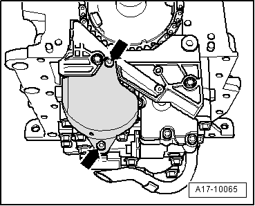
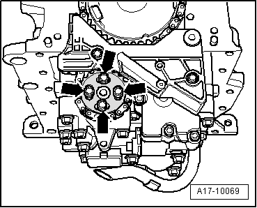
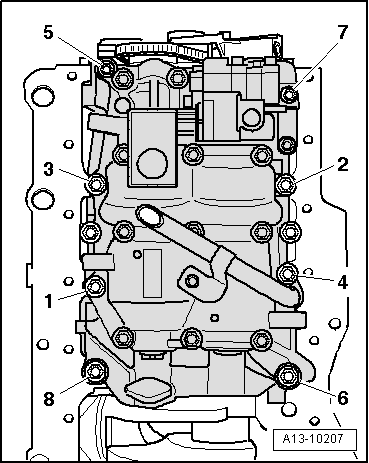
–  Unscrew bolts in the sequence -8 ... 1- and remove balance shaft assembly with oil pump.
Installing
  Note
Renew the bolts tightened with specified tightening angle and the chain sprocket for balance shaft assembly.
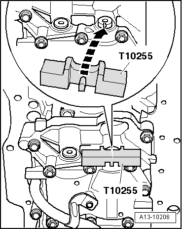
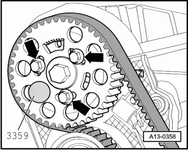
l  Toothed belt fitted.
l  
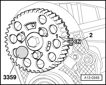
Camshaft locked with locking pin -3359-.
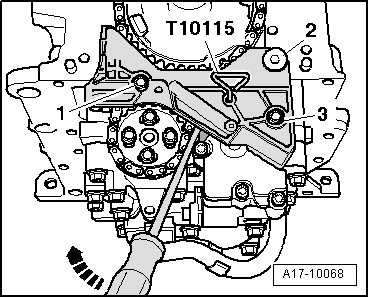
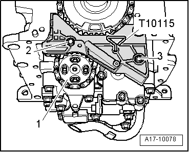
–  Tighten bolts securing balance shaft assembly as follows:
1.  Pre-tighten bolts in the sequence -1 ... 8- to 6 Nm.
2.  Tighten bolts -5- and -7- to 13 Nm.
3.  Turn bolts -5- and -7- 90° further using a rigid wrench.
4.  Tighten bolts -1 … 4-, -6- and -8- to 20 Nm.
5.  Turn bolts -1 ... 4-, -6- and -8- 90° further using a rigid wrench.
  A13-10207
–  Insert new sprocket -1- into chain – do not screw in securing bolts.
–  Initially screw in bolts -2- and -3- finger-tight, but do not tighten.
–  Remove locking pin -T10115- from chain tensioner.
  Note
  A17-10078
t  Before tightening the chain sprocket for the balance shaft assembly turn the de-coupling element in the drive chain sprocket to its central position. To do so, you must align the arrows marked on the drive chain sprocket and its de-coupling element.
t  However, these arrows are not visible with the sealing flange fitted. The following description explains how to achieve the central position without the aid of these arrows.
–  Turn chain sprocket -1- as far as right stop using counterhold -T10172--arrows-.
l  De-coupling element -2- of drive chain sprocket will be turned to right stop at the same time.
  A17-10111
–  In this position mark drive chain position -1- to hole -2- in balance shaft assembly.
  A17-10112
–  Use counterhold tool -T10172- to turn chain sprocket -1- back as far as left stop -arrows-.
l  De-coupling element -2- of drive chain sprocket will be turned to left stop at the same time.
  A17-10113
–  In this position mark present drive chain position -3- opposite hole -2- in balance shaft assembly.
  A17-10114
–  Then turn chain sprocket -1- back again, until de-coupling element -2- of drive chain sprocket is located in central position.
  Note
As the de-coupling element of the drive chain sprocket is not visible with the front sealing flange fitted, the central position is determined at the bottom of the drive chain.
  A17-10115
Determining central position of de-coupling element of drive chain sprocket with front sealing flange fitted.
–  The chain sprocket has to be turned back, until it reaches the central position exactly between the markings -1- and -3- on the drive chain.
l  Reference mark is again hole -2- on balance shaft assembly.
  A17-10116
–  Lock balance shaft with locking tool -T10255-.
l  The lug of the locking device must engage in the groove of the balance shaft, if necessary, turn the balance shaft.
  A13-10206
–  Check whether elongated holes of chain sprocket align with tapped holes of balance shaft.
If holes do not align:
–  Secure tensioner with locking pin -T10115- and unscrew bolts -2- and -3-.
–  Turn chain sprocket -1- in drive chain one tooth further.
–  Tighten bolts.
–  Remove locking pin -T10115-.
  A17-10078
–  Use new bolts to secure chain sprocket -arrows-.
–  Lock balance shaft with locking tool -T10255- and tighten bolts for chain sprocket initially to 10 Nm.
l  When doing this, make sure not to change position of chain sprocket and balance shaft, otherwise slacken bolts and once again move chain sprocket to its central position.
–  Turn bolts -arrows- for chain sprocket 90° further.
  A17-10069
–  Fit chain tensioner cover -arrows-.
  A17-10065
–  Remove locking pin -3359-.
  Note
Disregard -arrows-.
Remaining installation steps are carried out in reverse sequence; note the following:
–  Install sump → Chapter.
–  Fill up with engine oil and check oil level → Booklet803 or → Booklet805.
Tightening torques
  A13-0358
ComponentNm
Balance shaft assemblyM713 + 90° 1)
to cylinder blockM820 + 90° 1)
Chain tensioner to balance shaft assembly9
Chain sprocket to balance shaft10 + 90° 1)
Cover for Chain tensioner5 2)
chain sprocket to: Oil pump5 2)
l  1) Renew bolts.
l  2) Apply locking fluid when installing; refer to → Electronic parts catalogue for locking fluid.


Removing and installing oil pump > < Removing and installing sump