
A4 Mk2
| Piston with sawn conrod - exploded view |
 Note
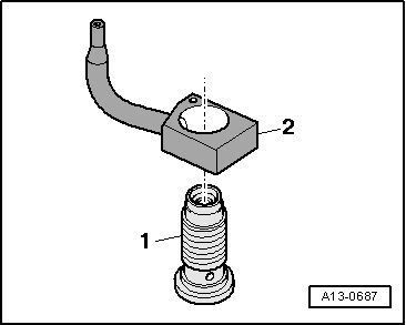
Note| Oil spray jet and pressure relief valve → Fig. |
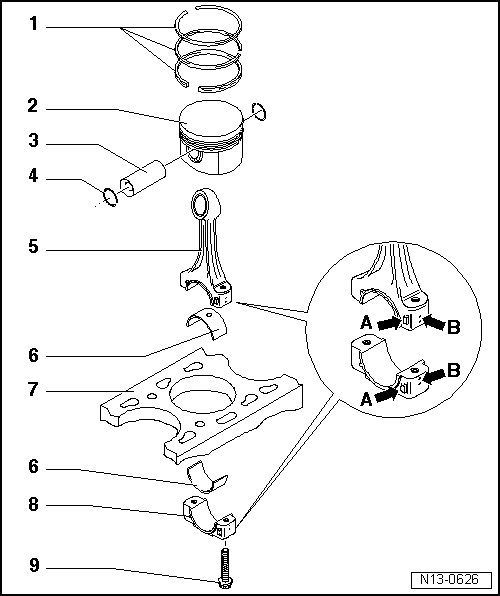
| 1 - | Piston rings |
| q | Offset gaps by 120° |
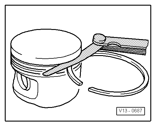
| q | Use piston ring pliers to remove and install |
| q | Marking “TOP” or inscription must face piston crown. |
| q | Measuring ring gap → Fig. |
| q | Measuring ring-to-groove clearance → Fig. |
| 2 - | Piston |
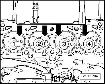
| q | Mark installation position and cylinder number |
| q | Installation position and allocation of piston/cylinder → Fig. |
| q | If cracking is visible on piston skirt, renew piston |
| q | Arrow on piston crown points to pulley end |
| q | Install using piston ring clamp |
| q | Measuring piston projection at TDC → Chapter |
| q | Piston and cylinder dimensions → Chapter |
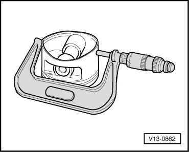
| q | Checking → Fig. |
| 3 - | Piston pin |
| q | If difficult to move, heat piston to approx. 60 °C |
| q | Remove and install using drift -VW 222 A- |
| 4 - | Circlip |
| 5 - | Conrod |
| q | Only renew as a complete set |
| q | Mark cylinder number -B- |
| q | Installation position: Markings -A- face towards pulley end |
| q | Measuring radial clearance → Chapter |
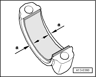
| 6 - | Bearing shell |
| q | Installation position → Fig. |
| q | Renew used bearing shells |
| q | Note version: Upper bearing shell (towards piston) made of a more wear-resistant material; new bearing shells can be identified by a black line on bearing surface in area of joint |
| q | Insert bearing shells centrally |
| q | Check that it is securely seated |
| q | Axial clearance: wear limit: 0.37 mm |
| q | Measuring radial clearance → Chapter |
| 7 - | Cylinder block |
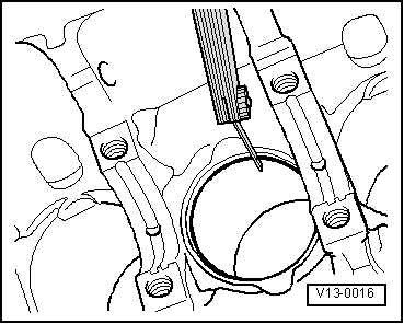
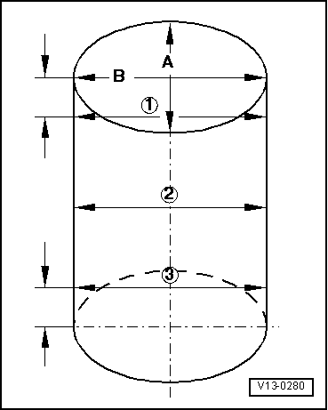
| q | Measuring cylinder bore → Fig. |
| q | Piston and cylinder dimensions → Chapter |
| 8 - | Conrod bearing cap |
| q | Mark cylinder number -B- |
| q | Installation position: Markings -A- face towards pulley end |
| 9 - | Conrod bolt, 30 Nm + turn 90° further |
| q | Renew |
| q | Lubricate threads and contact surface |
| Piston ring | new mm | Wear limit mm |
| 1st compression ring | 0.25 … 0.40 | 1.0 |
| 2nd compression ring | 0.25 … 0.40 | 1.0 |
| Oil scraper ring | 0.25 … 0.50 | 1.0 |
|
|
| Piston ring | new mm | Wear limit mm |
| 1st compression ring | 0.06 … 0.09 | 0.25 |
| 2nd compression ring | 0.05 … 0.08 | 0.25 |
| Oil scraper ring | 0.03 … 0.06 | 0.15 |
|
|
Note
|
|
|
|
|
|
|
|