A4 Mk2
| Sump, oil pump, balance shaft assembly with spur gear drive - exploded view |
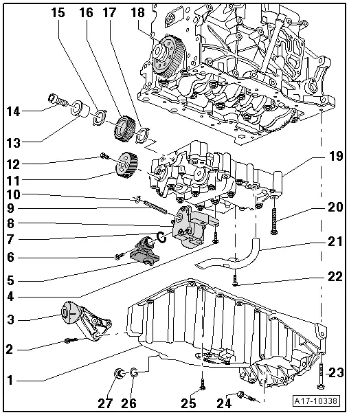
| 1 - | Sump |
| q | With oil level and oil temperature sender -G266- |
| q | Removing and installing sump → Chapter |
| 2 - | 23 Nm |
| 3 - | Torque reaction support |
| 4 - | 10 Nm |
| 5 - | Intake connecting pipe |
| q | Clean strainer if dirty |
| 6 - | 10 Nm |
| 7 - | O-ring |
| q | Renew |
| 8 - | Oil pump |
| q | Removing and installing → Chapter |
| q | Before installing, check that the two dowel sleeves for centring oil pump are fitted onto balance shaft assembly. |
| 9 - | Oil pump drive shaft |
| 10 - | Circlip |
| q | Must fit securely in groove |
| q | Renew circlip if damaged or stretched |
| 11 - | Spur gear for balance shaft |
| 12 - | 20 Nm + turn 90° further |
| q | Renew |
| 13 - | Hub |
| q | For idler gear |
| 14 - | 90 Nm + turn 90° further |
| q | Renew |
| 15 - | Thrust washer |
| q | For idler gear |
| q | Renew |
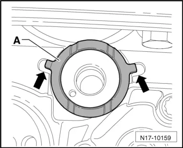
| q | Installation position → Fig. |
| 16 - | Idler gear |
| q | Renew |
| q | To achieve the correct backlash a suitably thick coating is already applied to the new idler gear |
| q | Installing → Chapter |
| 17 - | Thrust washer |
| q | For idler gear |
| 18 - | Spur gear |
| 19 - | Balance shaft assembly |
| q | Removing → Chapter |
| q | Installing new balance shaft assembly → Chapter |
| q | Re-installing "old" balance shaft assembly → Chapter |
| q | Before installing, check that the two dowel sleeves for centring balance shaft assembly are fitted onto cylinder block. |
| 20 - | Bolt |
| q | Renew |
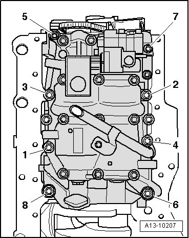
| q | Tightening torque and sequence with eight attachment points → Fig. |
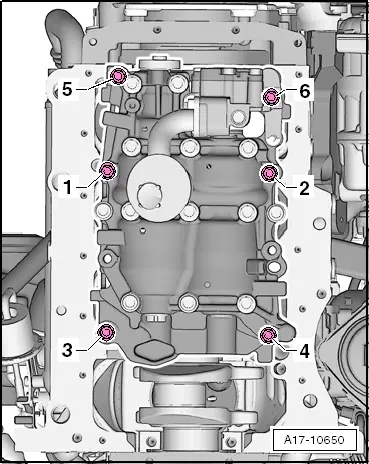
| q | Tightening torque and sequence with six attachment points → Fig. |
| 21 - | Oil intake pipe |
| 22 - | 10 Nm |
| 23 - | 40 Nm |
| q | Observe correct tightening sequence → Anchor |
| 24 - | 45 Nm |
| q | Observe correct tightening sequence → Anchor |
| 25 - | 15 Nm |
| q | Tighten in stages and in diagonal sequence |
| q | Observe correct tightening sequence → Anchor |
| 26 - | Seal |
| q | Renew |
| 27 - | Oil drain plug, 30 Nm |
|
|
| Stage | Bolts | Tightening torque/angle specification |
| 1. | -1 … 8- | hand-tighten |
| 2. | -1 … 8- | 6 Nm |
| 3. | -1 … 4- | 20 Nm |
| 4. | -5- | 13 Nm |
| 5. | -6- | 20 Nm |
| 6. | -7- | 13 Nm |
| 7. | -8- | 20 Nm |
| 8. | -1 … 8- | turn 90° further |
|
|
| Stage | Bolts | Tightening torque/angle specification |
| 1. | -1 … 6- | hand-tighten |
| 2. | -1 … 6- | 6 Nm |
| 3. | -1 … 4- | 20 Nm |
| 4. | -5, 6- | 13 Nm |
| 5. | -1 … 6- | turn 90° further |
 Caution