
Removing and Installing Turbocharger for 4-cylinder TDI Engine (BRD and BVA Codes)
 Caution
|
|
|
|
|
|
 Note
Note
|
|
Note
|
|
|
|
|
|
|
|
|
|
Note
|
|
|
|
Note |
|
|

|
|
|
Note
Note
Note
|
|
| Component | Nm | ||||
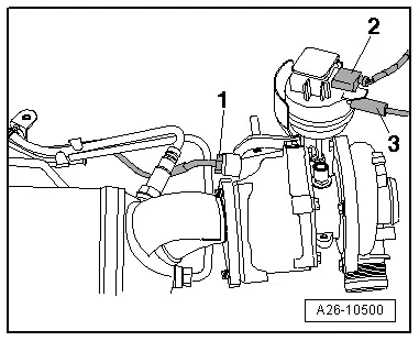
| Turbocharger to exhaust manifold | 25 1)2) | ||||
| Support for turbocharger to turbocharger | 20 | ||||
| Support for turbocharger to cylinder block | 40 | ||||
| Oil return pipe to cylinder block | 40 | ||||
| Oil supply pipe to turbocharger | 22 | ||||
| Bracket for oil supply pipe to exhaust manifold | 22 | ||||
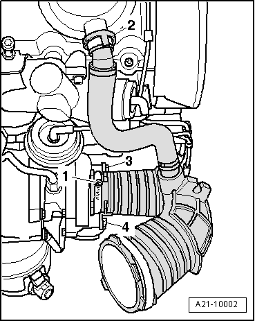
| Air intake hose to turbocharger | 8 | ||||
| Hose clips (9 mm wide) | 3.5 | ||||
| Hose clips (13 mm wide) | 5.5 | ||||
| |||||