
A4 Mk2
| Removing engine |
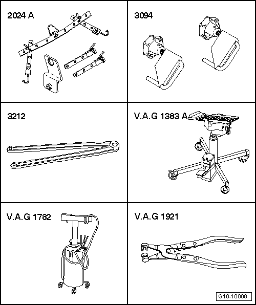
| Special tools and workshop equipment required |
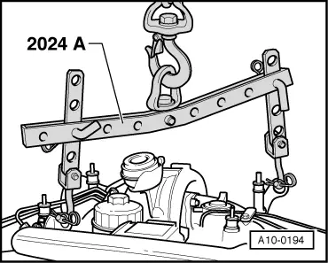
| t | Lifting tackle -2024 A- |
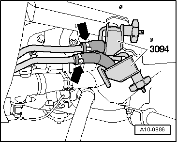
| t | Hose clamps for hoses up to 25 mm Ø -3094- |
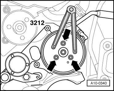
| t | Pin wrench -3212- |
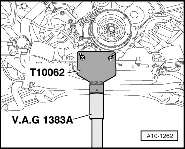
| t | Engine and gearbox jack -V.A.G 1383 A- |
| t | Used oil collection and extraction unit -V.A.G 1782- |
| t | Hose clip pliers -V.A.G 1921- |
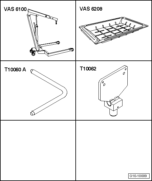
| t | Workshop hoist -VAS 6100- or workshop hoist -V.A.G 1202 A- |
| t | Drip tray for workshop hoist -VAS 6208- or drip tray -V.A.G 1306- |
| t | Locking pin -T10060- or -T10060 A- |
| t | Support -T10062- |
 Note
Note
|
 Caution
|
|
|
|
 WARNING
|
|
|
|
|
|
|
|
|
|
|
|
|
|
|
|
Note
Note
|
|
|
|
|
|
|
|
|
|
|
|
|
|
Note
|
|
|
|
Note
|
|
|
|
|
|
|
|
|
|
|
|
|
|
|
|
|
|
|
|
|
|
Note
|
|
Note |
|
Note |
|
|
|
Note
|
|
|
|
|
|
|
|
|
|
|
|
|
|
|
|
|
|
|
|
Note
|
|
|
|
|
|
Note
|
|
|
|
|
|
|
|
|
|
|
|
Note
|
|
Note
|
|
|
|
|
|
Note
|
|
Note
|
|
Note
|
|
Note
Note
Note
|
|
|
|