audi Workshop Repair Guides

Audi Workshop Service and Repair Manuals

Coolant pump and thermostat - exploded view of components > < Connection diagram for coolant hoses - vehicles without exhaust gas recirculation cooler and with auxiliary heater
Draining and filling cooling system
   
Draining and filling cooling system
Special tools and workshop equipment required
t  Adapter for cooling system tester -V.A.G 1274/8-
t  Pipe for cooling system tester -V.A.G 1274/10-
t  Drip tray for workshop hoist -VAS 6208- or -V.A.G 1306-
t  Hose clip pliers -V.A.G 1921-
t  Cooling system charge unit -VAS 6096-
t  Refractometer -T10007-

Draining
  Note
Collect drained coolant in a clean container for re-use or disposal.
  WARNING
Hot steam or hot coolant can escape when expansion tank is opened; cover filler cap with cloth and open carefully.
–  Open filler cap on coolant expansion tank.
   
–  On vehicles with auxiliary/additional heater, remove bolts -arrows- securing exhaust pipe for auxiliary/additional heater to noise insulation.
  A10-0407
–  Release quick-fasteners -1- and -2- and take off front noise insulation. Leave rear noise insulation in position.
  A10-1320
–  Place drip tray for workshop hoist -VAS 6208- or -V.A.G 1306- under engine.
Vehicles with coolant drain plug:
–  Unscrew coolant drain plug -1- in coolant hose connection -2- and drain coolant (fit hose to hose connection if necessary).
  A10-1082
Vehicles without coolant drain plug:
–  Pull off retaining clip -1- on coolant temperature sender.
–  Pull coolant temperature sender out of coolant hose connection and drain off coolant.
All vehicles:
–  Open coolant drain plug -2- at coolant pipe and let coolant drain.
  A10-0273
–  Pull off engine cover panel -arrows-.
  A34-0371
–  Unbolt coolant expansion tank -arrow-.
–  Unplug electrical connector for coolant shortage indicator switch -F66- at expansion tank (bottom) and move expansion tank to one side (coolant hoses -1 ... 3- remain attached).
  A10-0989
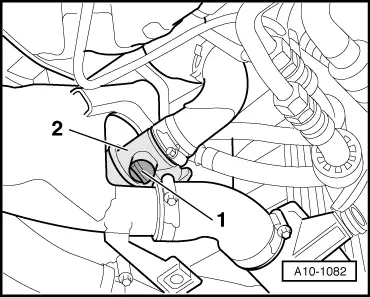
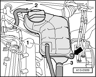
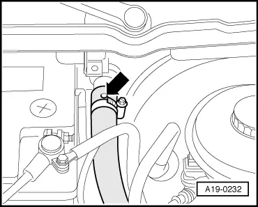
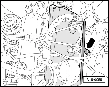
–  Disconnect coolant hose -arrow- and press hose downwards to drain off remaining coolant.
Filling
  Note
t  The cooling system is filled all year round with a mixture of water and radiator antifreeze/anti-corrosion agent.
t  It is important to use only coolant additive Plus -G 012 A8F A1- (also designated as “G12+”) “meeting specification TL VW 774 F”. Other coolant additives could seriously impair in particular the anticorrosion properties. The resulting damage could lead to loss of coolant and consequently to serious engine damage.
t  Coolant additive “G12+” may be mixed with additives “G11” and “G12”.
t  “G12+” and coolant additives marked “Conforming with specification TL VW 774 F” prevent frost and corrosion damage and stop scale from forming. Such additives also raise the boiling point of the coolant. For these reasons the cooling system must be filled all year round with the correct antifreeze and anticorrosion additive.
t  Because of its high boiling point, the coolant improves engine reliability under heavy loads, particularly in countries with tropical climates.
t  Frost protection is required down to about –25 °C (in countries with arctic climate: down to about –35 °C).
t  
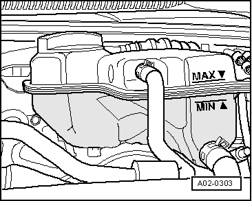
The coolant concentration must not be reduced by adding water even in warmer seasons and in warmer countries. The antifreeze concentration must be at least 40 %.
t  If greater frost protection is required in very cold climates, the amount of “G12+” can be increased, but only up to 60% (this gives frost protection to about –40 °C). If antifreeze concentration exceeds 60%, frost protection decreases again and cooling efficiency is also impaired.
t  Use only clean tap water for mixing coolant.
t  If radiator, heat exchanger, cylinder head, cylinder head gasket or cylinder block have been renewed, do not re-use old coolant.
t  Contaminated or dirty coolant must not be used again.
t  
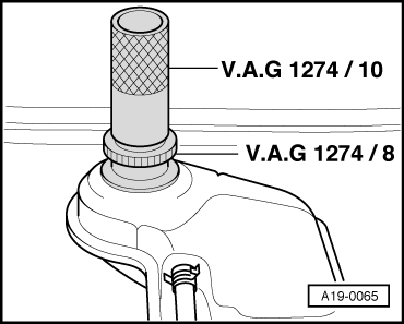
To check frost protection level of coolant additive “G12+” you must use a refractometer -T10007-.
t  
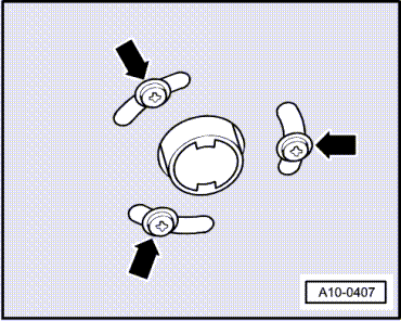
Secure all hose connections with the correct type of hose clips (same as original equipment) → Parts catalogue.
t  Renew seals and O-rings.
  A19-0089
Procedure
–  Fit coolant hose -arrow- onto coolant pipe.
  A19-0089
Vehicles with coolant drain plug:
–  Tighten coolant drain plug -1- in coolant hose connection -2-.
  A10-1082
Vehicles without coolant drain plug:
–  Insert coolant temperature sender -1- with new O-ring into coolant hose connection and secure with retaining clip -1-.
All vehicles:
–  Renew seal and tighten coolant drain plug -2- to 10 Nm.
  A10-0273
–  Fill reservoir -VAS 6096/1- with at least 14 litres of premixed coolant (based on recommended ratio):
l  “G12+” (40 %) and water (60 %) for frost protection to -25 °C
l  “G12+” (50 %) and water (50 %) for frost protection to -35 °C
l  “G12+” (60 %) and water (40 %) for frost protection to -40 °C
–  Screw adapter for cooling system tester -V.A.G 1274/8- onto coolant expansion tank.
–  Attach cooling system charge unit -VAS 6096- onto adapter -V.A.G 1274/8-.
–  Run vent hose -1- into a small container -2-. (The vented air draws along a small amount of coolant, which should be collected.)
–  Close the two valves -A- and -B- by setting lever at right angle to direction of flow.
–  Connect hose -3- to compressed air.
l  Pressure: 6 ... 10 bar.
  A19-0351
–  Open valve -B- by setting lever in direction of flow.
The suction jet pump generates a partial vacuum in the cooling system.
l  The needle on the gauge should move into the green zone.
–  Also briefly open valve -A- (turn lever in direction of flow) so that hose on reservoir -VAS 6096/1- can fill with coolant.
–  Close valve -A- again.
–  Leave valve -B- open for another 2 minutes.
l  The suction jet pump will continue generating a vacuum in the cooling system.
l  The needle on the gauge should remain in the green zone.
–  Close valve -B-.
l  The needle on the gauge should stop in the green zone. The vacuum level in the cooling system is then sufficient for subsequent filling.
If the needle does not reach the green zone, repeat the process.
If the vacuum level drops, there is a leak in the cooling system.
–  Detach compressed air hose.
–  Open valve -A-.
The partial vacuum in the cooling system causes the coolant to be drawn up out of the reservoir -VAS 6096/1-; the cooling system is then filled.
–  Detach cooling system charge unit -VAS 6096- from expansion tank.
  A19-0353
–  Fit pipe -V.A.G 1274/10- onto adapter -V.A.G 1274/8-.
  A19-0065
–  If fitted, detach rubber seal from plenum chamber cover in direction of -arrow-.
–  Detach plenum chamber cover -1- towards the front.
  A20-0564
–  Release coolant hose going to heat exchanger and pull back hose until bleeder hole in hose -arrow- is no longer blocked by the connection.
–  Fill up with coolant until it flows out at bleeder hole in coolant hose.
–  Push coolant hose onto connection and secure with hose clip.
–  On vehicles with auxiliary heater, switch heater on (for about 30 seconds) and then off again.
–  Tighten filler cap on expansion tank.
–  Start engine.
–  Set heater/air conditioner to “HI”.
–  Run the engine for 3 minutes at 2000 rpm.
–  Allow the engine to run at idling speed until the two large coolant hoses at main radiator become warm.
–  Run the engine for 1 minute at 2000 rpm.
–  Switch off ignition and allow engine to cool down.
  A19-0232
–  Check coolant level.
l  The coolant level must be at the MAX marking when the engine is cold.
l  The coolant level can be above the MAX marking when the engine is warm.
  A02-0303

Coolant pump and thermostat - exploded view of components > < Connection diagram for coolant hoses - vehicles without exhaust gas recirculation cooler and with auxiliary heater