
A4 Mk2
| Removing, installing and checking thermostat |

| Special tools and workshop equipment required |
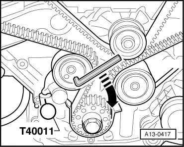
| t | Locking pin -T40011- |
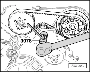
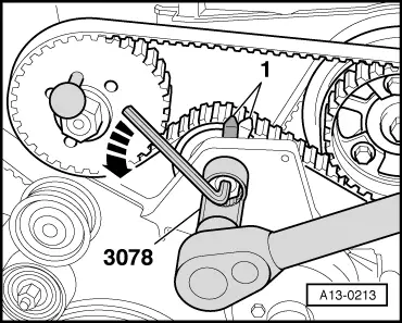
| t | Socket (22 mm) -3078- |
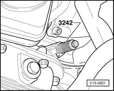
| t | Locking pin -3242- |
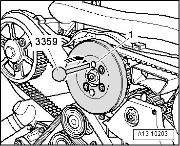
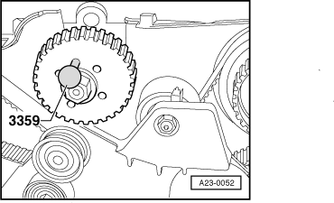
| t | Diesel injection pump locking pin -3359- |
| t | Locking fluid → Parts catalogue |
|
 Note
Note
|
|
 Caution
|
|
Note
|
|
 WARNING
Note |
|
|
|
|
|
Note
|
|
|
|
Note
|
|
|
|
Note
|
|
|
|
|
|
|
|
|
|
|
|
|
|
Note
|
|
|
|
|
|
|

|
| Component | Nm | ||
| Thermostat housing to cylinder block | 10 → Note | ||
| Viscous fan pulley to hub | 10 | ||
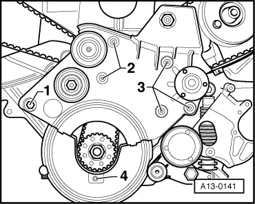
| Tensioning roller for injection-pump toothed belt to bracket for viscous fan | 36 | ||
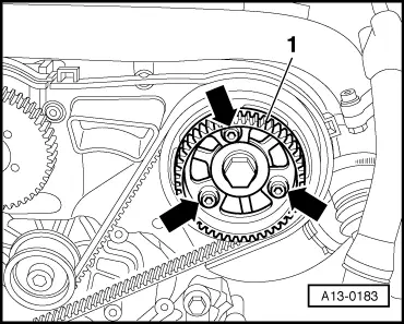
| Drive sprocket for injection pump to camshaft | 22 | ||
| Screw plug in cylinder block | M6 | 10 | |
| M18 | 35 | ||
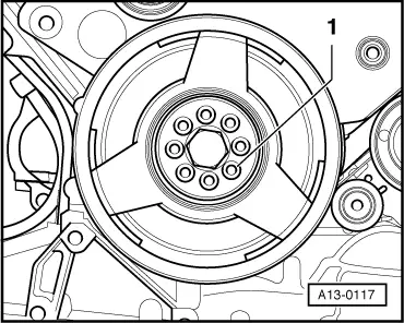
| Vibration damper to injection pump sprocket | 22 | ||
| Toothed belt cover (rear) to | Cylinder head | 10 | |
| Injection pump | 10 | ||
| Vibration damper to crankshaft sprocket | 22 | ||
|
| Starts to open | Fully open | Opening travel |
| approx. 87 °C | approx. 102 °C → Note | at least 8 mm |
|