audi Workshop Repair Guides

Audi Workshop Service and Repair Manuals

Checking compression > < Removing cylinder head (right-side)
Installing cylinder head
Special tools and workshop equipment required
   
t  Locking pin -3242-
  W00-0293
t  Camshaft clamp -3458-
Procedure
  Note
t  Renew the cylinder head bolts.
t  Renew self-locking nuts and bolts when performing assembly work.
t  Renew bolts which are tightened to a specified angle as well as oil seals, gaskets and O-rings.
t  Carefully remove any sealant residue from the cylinder head and cylinder block. Ensure that no long scores or scratches are made on the surfaces.
t  Carefully remove any remaining emery and abrasive material.
t  No oil or coolant must be allowed to remain in the blind holes for the cylinder head bolts in the cylinder block.
t  Do not remove new cylinder head gasket from packaging until it is ready to be fitted.
t  Handle gasket very carefully. Damage to the silicone coating or the indented area will lead to leaks.
t  Position cylinder head gasket on dowel sleeves. The word “oben” (top) or the Part No. should face towards the cylinder head.
t  The plastic protectors fitted to protect the open valves should not be removed until the cylinder head is ready to be fitted.
t  When installing an exchange cylinder head with fitted camshafts, oil the contact surfaces between the rocker fingers and cams.
t  After working on the valve gear, turn the engine carefully at least 2 rotations to ensure that none of the valves make contact when the starter is operated.
t  Secure all hose connections with the correct type of hose clips (same as original equipment) → Parts catalogue.
–  Set crankshaft and camshaft to TDC before fitting cylinder head.
  W00-0424
l  It should be possible to insert camshaft clamp -3458- into camshaft.
  A13-0120
l  Locking pin -3242- must be screwed in with crankshaft at TDC position.
  V13-0831
–  Note identification markings on cylinder head gasket.
-Arrow 1- = holes
-Arrow 2- = Part No.
-Arrow 3- = production control code (can be disregarded)
  Note
t  If the cylinder head gasket or cylinder head have been replaced, select the new cylinder head gasket according to the number of holes on the old gasket.
t  If parts of the crankshaft drive have been renewed, the new cylinder head gasket must be selected by measuring the piston projection at TDC → Chapter.
–  Renew O-rings for coolant pipes before installing cylinder head.
–  Fit cylinder head gasket.
l  Note position of centring pins in cylinder block.
l  Check installation position of cylinder head gasket: the word “oben” (top) or the Part No. should face towards the cylinder head.
–  Fit the cylinder head.
–  Insert new cylinder head bolts and tighten finger-tight.
  A13-0143
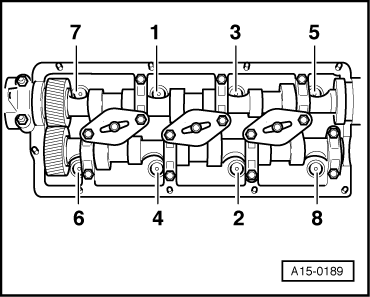
–  Tighten cylinder head bolts as follows in the sequence shown:
Tighten using torque wrench:
1.  stage: 35 Nm
2.  stage: 60 Nm
Tighten using rigid spanner:
3.  stage: 90° (1/4 turn) further
4.  stage: 90° (1/4 turn) further
  Note
Cylinder head bolts do not have to be torqued down again later after repair work.
Remaining installation steps are carried out in reverse sequence; note the following:
–  Install cylinder head cover: left-side → Chapter, right-side → Chapter.
–  When installing right cylinder head, renew O-ring at base of dipstick guide tube. To do this, take off poly V-belt, loosen alternator mounting bolts and pivot alternator to the side.
–  Install coolant pipe (right-side) → Chapter.
Vehicles with engine code letters AKE, AYM, BAU, BCZ, BFC:
–  Install coolant pipe (top and bottom left) → Chapter.
Vehicles with engine code letters BDG, BDH:
–  Install coolant pipe (top left) → Chapter.
–  Install coolant pipe (bottom left) → Chapter.
All vehicles:
–  Install coolant pipe (front) → Chapter.
–  Install exhaust manifold together with intermediate pipe: left-side → Chapter, right-side → Chapter.
–  Install starter catalytic converter: vehicles with front-wheel drive → Chapter, vehicles with four-wheel drive → Chapter.
–  Install front exhaust pipe with main catalytic converter: vehicles with front-wheel drive → Chapter, vehicles with four-wheel drive → Chapter.
–  Install intake manifold (front section) → Rep. Gr.23.
–  Install toothed belt (adjust valve timing) → Anchor.
–  Install viscous fan → Chapter.
–  Install lock carrier with attachments → General body repairs, exterior; Rep. Gr.50.
–  Install front bumper cover → General body repairs, exterior; Rep. Gr.63.
–  Fill cooling system → Anchor.
–  Observe notes on procedures required after connecting battery → Electrical system; Rep. Gr.27.
Tightening torques
  A15-0189
ComponentNm
Guide tube for dipstick to cylinder head10
Oil pipe to:Turbocharger15
 Intake manifold22
Toothed belt cover toCylinder head10
 Injection pump10
Heat shield to turbocharger10


Checking compression > < Removing cylinder head (right-side)