audi Workshop Repair Guides

Audi Workshop Service and Repair Manuals

Renewing valve stem oil seals with cylinder head removed > < Removing and installing outer camshaft bearing caps
Renewing valve stem oil seals with cylinder head installed
   
Renewing valve stem oil seals with cylinder head installed
Special tools and workshop equipment required
t  U/J extension and socket, 10 mm -3220-
t  Valve stem seal puller -3364-
t  Valve stem seal fitting tool -3365-
t  Removal and installation device for valve cotters -VAS 5161-

   
Removing
–  On vehicles with auxiliary/additional heater, remove bolts -arrows- securing exhaust pipe for auxiliary/additional heater to noise insulation.
  A10-0407
–  Open quick-release fasteners -1 … 3- and take off front and rear noise insulation.
–  Remove front bumper cover → General body repairs, exterior; Rep. Gr.63.
–  Move lock carrier into its service position → General body repairs, exterior; Rep. Gr.50.
–  Detach toothed belt from camshaft sprockets → Chapter.
–  Remove camshafts → Chapter.
–  Remove roller rocker fingers.
–  Detach electrical connectors at glow plugs.
–  Unscrew all glow plugs using U/J extension and socket, 10 mm -3220-.
  A10-1320
–  Fit guide plate -VAS 5161/9- onto cylinder head.
–  Secure guide plate onto cylinder head using knurled screws -VAS 5161/12-.
–  Insert punch -VAS 5161/3- into guide plate.
–  Use plastic-headed hammer to release locked valve cotters on all four valves.
  A15-0490
–  Screw sealing pin -VAS 5161/10- into guide plate.
–  Screw adapter -VAS 5161/11- finger-tight into the glow plug hole of the relevant cylinder.
  A15-0495
–  Screw snap-in device -VAS 5161/6- with -VAS 5161/5- into guide plate -VAS 5161/9-.
–  Slide knurled spacer ring -VAS 5161/17- onto assembly cartridge -VAS 5161/8-.
–  Connect adapter -VAS 5161/11- to compressed air supply using a standard connection fitting.
l  Air pressure: at least 6 bar
–  Attach pressure fork -VAS 5161/2- to snap-in device -VAS 5161/6- and push assembly cartridge down.
–  At the same time, turn knurled screw of assembly cartridge clockwise until tips engage in valve cotters.
–  Move knurled screw back and forth slightly; the valve cotters are thus forced apart and taken up by the cartridge.
–  Release the pressure fork.
–  Remove valve spring and valve spring plate (magnet).
  A15-0491
–  Pull off valve stem oil seal with valve stem seal puller -3364-.
  A15-0492
If the valve stem seal puller -3364- cannot be used on some of the valve stem oil seals due to the confined space, proceed as follows:
–  Knock out pin -arrow- from valve stem seal puller -3364- using a punch and remove the extractor attachment.
  A15-0493
–  Apply lower part of valve stem seal puller -3364- to valve stem oil seal.
–  Secure puller with a punch -1- or other suitable tool as shown in the illustration.
–  Apply assembly lever to puller and pull out valve stem oil seal -arrow-.
  A15-0494
Installing
  Note
A plastic sleeve -A- is included with the new valve stem oil seals.
–  To prevent damage to the new valve stem seals -B-, attach plastic sleeve -A- to valve stem.
  Note
The illustration is a schematic diagram of the procedure; other tools are not shown.
–  Lightly lubricate sealing lip of valve stem oil seal.
–  Slip valve stem oil seal over plastic sleeve.
–  Carefully press valve stem oil seal onto valve guide using valve stem seal fitting tool -3365-.
–  Remove the plastic sleeve.
  A15-0282
–  If valve cotters have been removed from assembly cartridge, they need to be put into insertion device -VAS 5161/18- first.
l  Larger diameter of valve cotters faces upwards.
–  Press assembly cartridge -VAS 5161/8- onto insertion device from above and pick up valve cotters.
  A15-0445
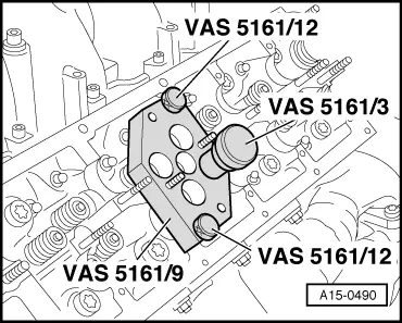
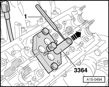
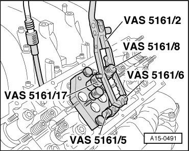
–  Re-insert assembly cartridge into guide plate -VAS 5161/9-.
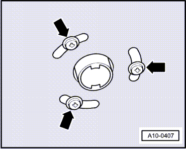
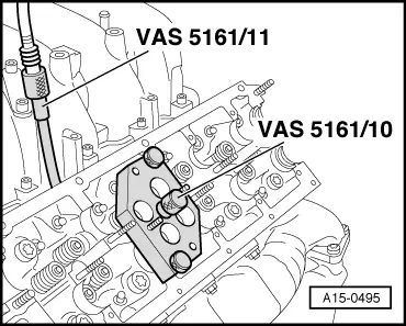
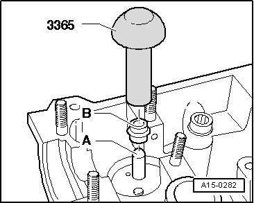
–  Push pressure fork down and pull knurled screw upwards, while turning screw in both directions – this will insert the valve cotters.
–  Release the pressure fork with knurled screw still in pulled position.
–  Install camshafts → Chapter.
–  Install glow plugs → Rep. Gr.28.
–  Install toothed belt (adjust valve timing) → Anchor.
–  Install viscous fan → Chapter.
–  Install lock carrier with attachments → General body repairs, exterior; Rep. Gr.50.
–  Install front bumper cover → General body repairs, exterior; Rep. Gr.63.
  Note
t  After installing camshafts, wait for approx. 30 minutes before starting engine. Hydraulic valve compensation elements have to settle (otherwise valves will strike pistons).
t  After working on the valve gear, turn the engine carefully at least 2 rotations to ensure that none of the valves make contact when the starter is operated.
  A15-0491

Renewing valve stem oil seals with cylinder head removed > < Removing and installing outer camshaft bearing caps