
A4 Mk2
| Valve gear - exploded view of components |
 Note
Note| t | After installing camshafts, wait for approx. 30 minutes before starting engine. Hydraulic valve compensation elements have to settle (otherwise valves will strike pistons). |
| t | After working on the valve gear, turn the engine carefully at least 2 rotations by hand to ensure that none of the valves make contact when the starter is operated. |
| t | The following illustration shows the left-side cylinder head. |
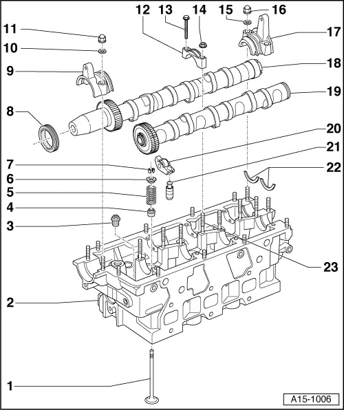
| 1 - | Valve |
| q | Checking → Chapter |
| q | Valve dimensions → Chapter |
| q | Remove and install with cylinder head removed using valve spring compressor -2037- |
| 2 - | Cylinder head |
| q | Removing: left-side → Chapter; right-side → Chapter |
| q | Installing → Chapter |
| q | Do not machine valve seats |
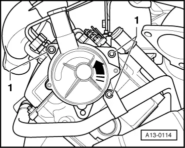
| q | With exhauster pump for brake servo |
| q | Removing and installing exhauster pump → Fig. |
| 3 - | Pressure limiting valve |
| q | For lubricating points in cylinder head |
| q | Tighten to 25 Nm |
| 4 - | Valve stem oil seal |
| q | Renewing valve stem oil seals with cylinder head installed → Chapter |
| q | Renewing valve stem oil seals with cylinder head removed → Chapter |
| 5 - | Valve spring |
| 6 - | Valve spring plate |
| 7 - | Valve cotters |
| 8 - | Oil seal |
| q | Renewing → Chapter |
| 9 - | Camshaft bearing caps for inlet camshaft |
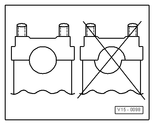
| q | Before fitting, apply sealant to sealing surfaces of outer bearing caps → Chapter |
| q | Installation sequence → Chapter |
| 10 - | Seal |
| q | Renew |
| 11 - | Cap nut, 15 Nm |
| 12 - | Camshaft bearing caps |
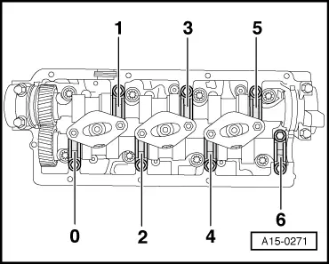
| q | Installation position → Fig. |
| q | Installation sequence → Chapter |
| 13 - | 10 Nm |
| 14 - | 10 Nm |
| 15 - | Seal |
| q | Renew |
| 16 - | Cap nut, 15 Nm |
| 17 - | Camshaft bearing caps for inlet camshaft |
| q | Before fitting, apply sealant to sealing surfaces of outer bearing caps → Chapter |
| q | Installation sequence → Chapter |
| 18 - | Inlet camshaft |
| q | Removing and installing → Chapter |
| q | Checking axial clearance → Chapter |
| q | Check radial clearance with Plastigage (roller rocker fingers removed) |
| q | Radial clearance when new: 0.035 ... 0.085 mm; Wear limit 0.10 mm |
| q | Runout: max. 0.04 mm |
| 19 - | Exhaust camshaft |
| q | Removing and installing → Chapter |
| q | Checking axial clearance → Chapter |
| q | Check radial clearance with Plastigage (roller rocker fingers removed) |
| q | Radial clearance when new: 0.035 ... 0.085 mm; Wear limit 0.10 mm |
| q | Runout: max. 0.04 mm |
| 20 - | Roller rocker finger |
| q | Mark installation position with a coloured pen |
| 21 - | Hydraulic valve compensation element |
| q | Mark installation position with a coloured pen |
| q | Checking → Chapter |
| q | Lubricate contact surface before fitting |
| 22 - | Thrust washers |
| q | 2x |
| 23 - | Stud |
| q | For bearing cap |
| q | Secure only hand-tight |
|
|
|
|
|
|