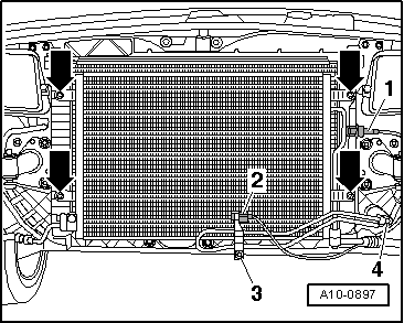
audi Workshop Repair Guides

Audi Workshop Service and Repair Manuals

Removing and installing radiator cowl > < Removing and installing coolant pipe (top) - not applicable for USA vehicles
Removing and installing radiator
Special tools and workshop equipment required
   
t  Drip tray for workshop hoist -VAS 6208-
  W00-10228
t  Used oil collection and extraction unit -V.A.G 1782-
  W00-10211
Removing
  Note
Even when the radiator and condenser are correctly installed, slight impressions may be visible on the fins of these components. This does not mean that the components are damaged. If the fins are only very slightly distorted, this does not justify renewal of the radiator or the condenser.
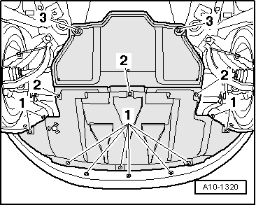
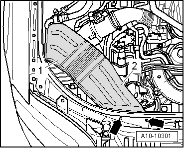
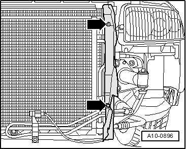
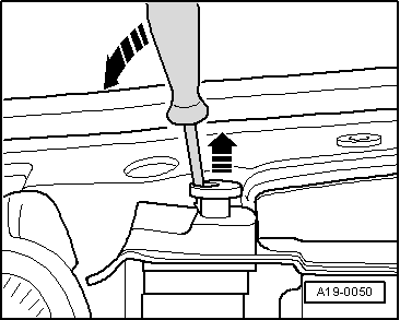
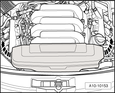
–  Pull off engine cover panel (front) -arrows-.
  WARNING
Hot steam or hot coolant can escape when expansion tank is opened; cover filler cap with cloth and open carefully.
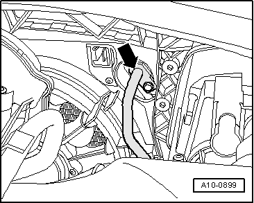
–  Open filler cap on coolant expansion tank.
  A10-10153
–  Vehicles with auxiliary heater: remove bolts -arrows- securing exhaust pipe for auxiliary/additional heater to noise insulation.
  A10-0407
–  Release quick-fasteners -1- and -2- and take off front noise insulation. Leave rear noise insulation in position.
–  Remove bumper cover (front) → Rep. Gr.63.
  A10-1320
–  Place drip tray for workshop hoist -VAS 6208- under engine.
–  Disconnect coolant hose -arrow- at bottom left of radiator and drain off coolant.
  A19-10078
–  Detach coolant hose (bottom right) from radiator -arrow-.
  A19-10119
–  Detach coolant hose (top) -arrow on right- from radiator.
  Note
Ignore -arrow on left side of illustration-.
  A10-10110
Vehicles with automatic gearbox:
–  Remove bolts -arrows-.
–  Remove air ducts -1- and -2-.
  Note
  A10-10301
Observe rules for cleanliness when working on automatic gearbox → Rep. Gr.00.
–  Place used oil collection and extraction unit -V.A.G 1782- under engine.
–  Detach ATF pipes (top -arrow- and bottom) from radiator: → Rep. Gr.37.
–  Tie ATF pipes up onto longitudinal member to prevent fluid escaping.
  A10-0899
All vehicles:
–  Unplug electrical connectors (left and right) -3- for horns -2-.
  Note
Disregard -item 1-.
  A96-10143
–  Remove cross member for bumper -arrows-.
  A63-10005
–  Unbolt air cowls (left and right) at radiator -arrows-.
  A10-0896
–  Unclip ambient temperature sensor -G17--item 2- from bracket.
–  Unscrew bolts -3- and -4- for power steering cooling pipe; the hydraulic hoses remain attached.
–  Detach electrical connector -1- at high-pressure sender -G65-.
  WARNING
The air conditioner refrigerant circuit must not be opened.
–  Remove bolts -arrows-.
  Note
To prevent damage to the refrigerant lines, ensure that the pipes and hoses are not stretched, kinked or bent.
–  Pivot condenser downwards with pipes/hoses attached.
  A10-0897
–  Release two retaining pins for radiator and pull out upwards -arrows-.
–  Swivel radiator forwards and lift off.
  A19-0050
Installing
Installation is carried out in the reverse order; note the following:
–  Remove old O-ring -2- from coolant hose -3-.
–  Lubricate new O-ring with coolant additive and fit O-ring in coolant hose.
–  Press coolant hose onto radiator -1- until it engages with a click.
–  Press coolant hose in again and then pull to check that plug-in connector is correctly engaged.
–  Install ATF pipes → Rep. Gr.37.
–  Install cross member for front bumper → Rep. Gr.63.
–  Install bumper cover (front) → Rep. Gr.63.
–  Fill cooling system → Anchor.
  Note
The coolant in the entire system must be changed if the radiator is renewed.
–  Check ATF level → Rep. Gr.37.
Tightening torques
  A19-10572
ComponentNm
Condenser to lock carrier6
Power steering cooling pipe to condenser9


Removing and installing radiator cowl > < Removing and installing coolant pipe (top) - not applicable for USA vehicles